This is the build log for my LED totem project. It took months of work to build and I barely got it done in time for EDC 2016.

It all started with an idea. What if I made a totem with a ton of LEDs? I did some research on the geometry of geodesic spheres and created a quick mock up in CAD. Originally I was looking at 1 LED per panel.

But 3 LEDs per panel seemed to look a lot better. And it would give me a lot more resolution to work with.
For this project I'm using WS2812 LEDs. They are also known as neopixel LEDs over at Adafruit. The cool thing about these is that they only need a common power and ground and a single data line to chain them together. So instead of needing 3x540 PWM signals from my microprocessor I just need a single pin (I actually divided it up between 4).

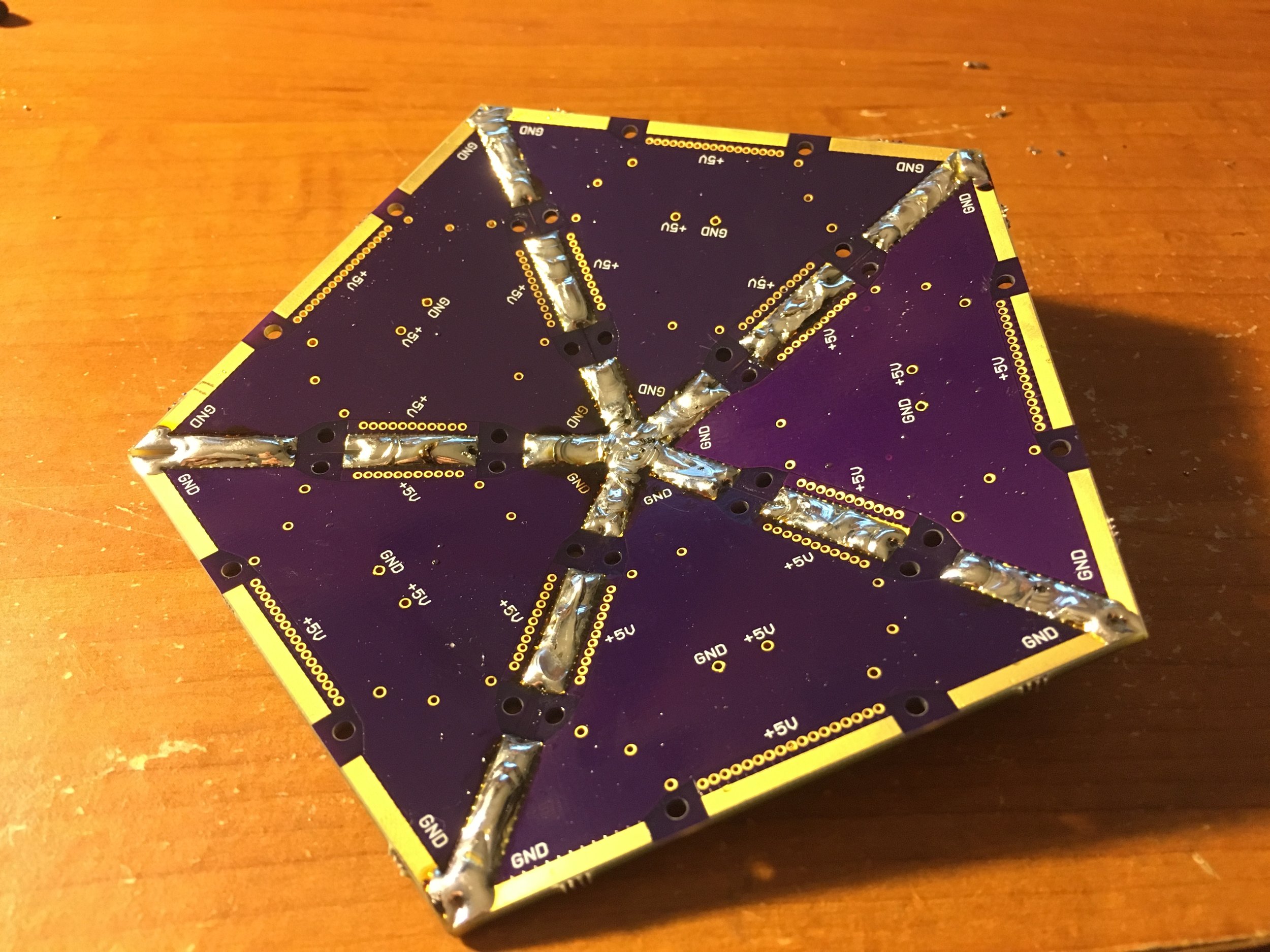
I started figuring out LED positioning and how I could have a common power and ground plane across the whole sphere. I did this in solid modeling software because it's a lot easier to make changes with parametric modeling. Circuit board layout programs are a lot less flexible. This side shows the power plane.

And this side shows the ground plane and power plane connections (everything is soldered on the back side).

The model started to get a lot more complex.

And I started work on what would become the internal structure. I couldn't just rely on the solder connections to hold everything together.

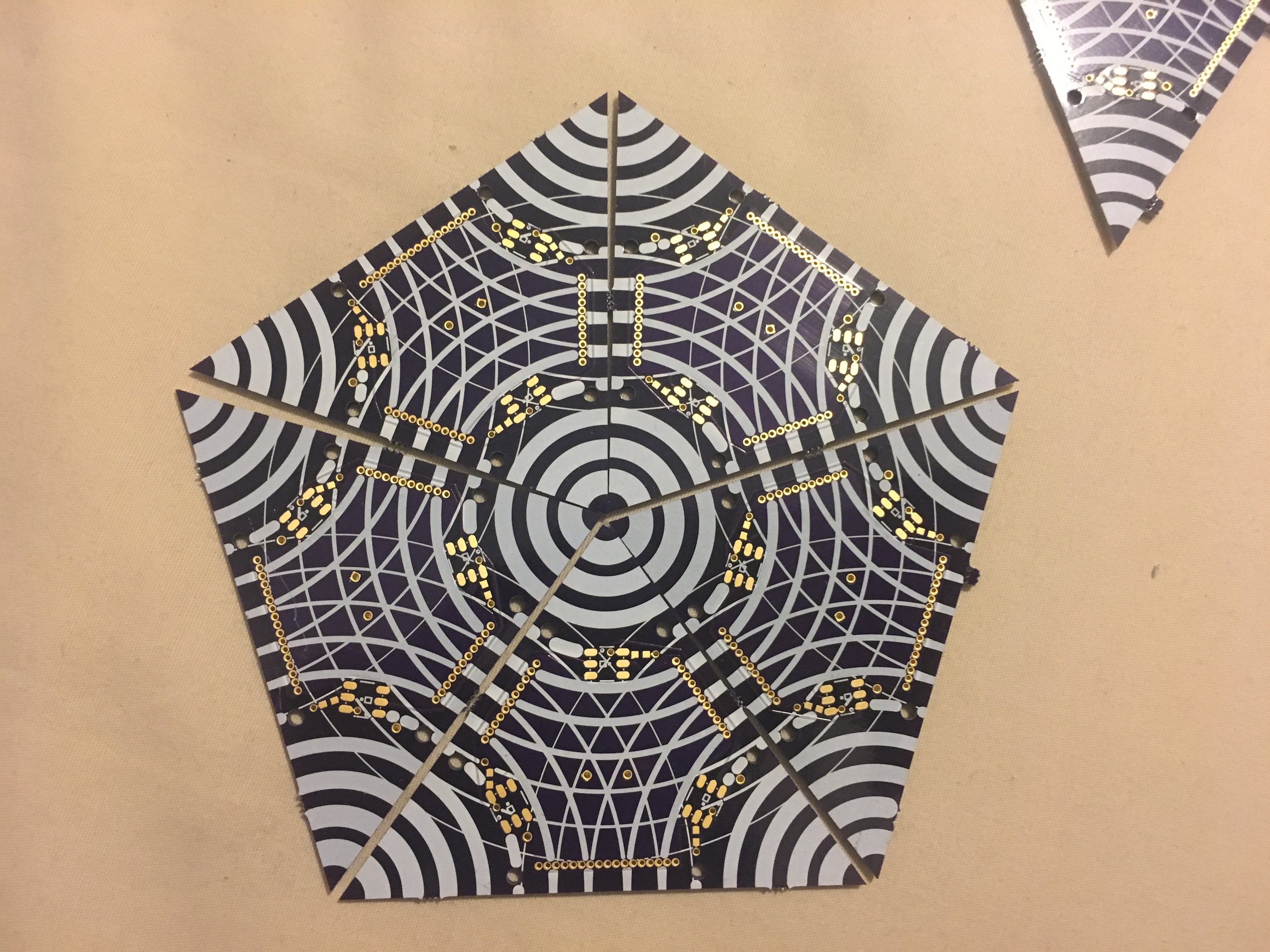
This was one of the initial versions of the board layout.
I ordered the prototype boards through OSH Park. They're super fast and high quality and I've used them for several projects now. However they charge $5 per sq. in. and you get 3 boards.

While the quality and speed are great, this initial prototype run of 6 cost me $60. To get the 180 boards I needed would be way to expensive. Also, OSH only has one thickness option: the standard .062". To save on weight I wanted to get .031" boards.
On the back side you can see how the boards are soldered together. They're actually surprisingly strong!

Unfortunately I realized too late that the LED footprint was wrong. I had used the footprint for the WS2812 LEDs, and didn't notice that I ordered the updated WS2812Bs... Completely incompatible but I could still solder the boards together to see how that worked.
I also wasn't too happy with the silk screen pattern, so I made some modifications for the next batch.

Along with the prototype boards I also designed and ordered these little guys. It's a low voltage cutoff circuit to protect my LiPo batteries from draining too far. If the batteries ever drop below 3.0V per cell they can be permanently damaged and never hold a charge again.
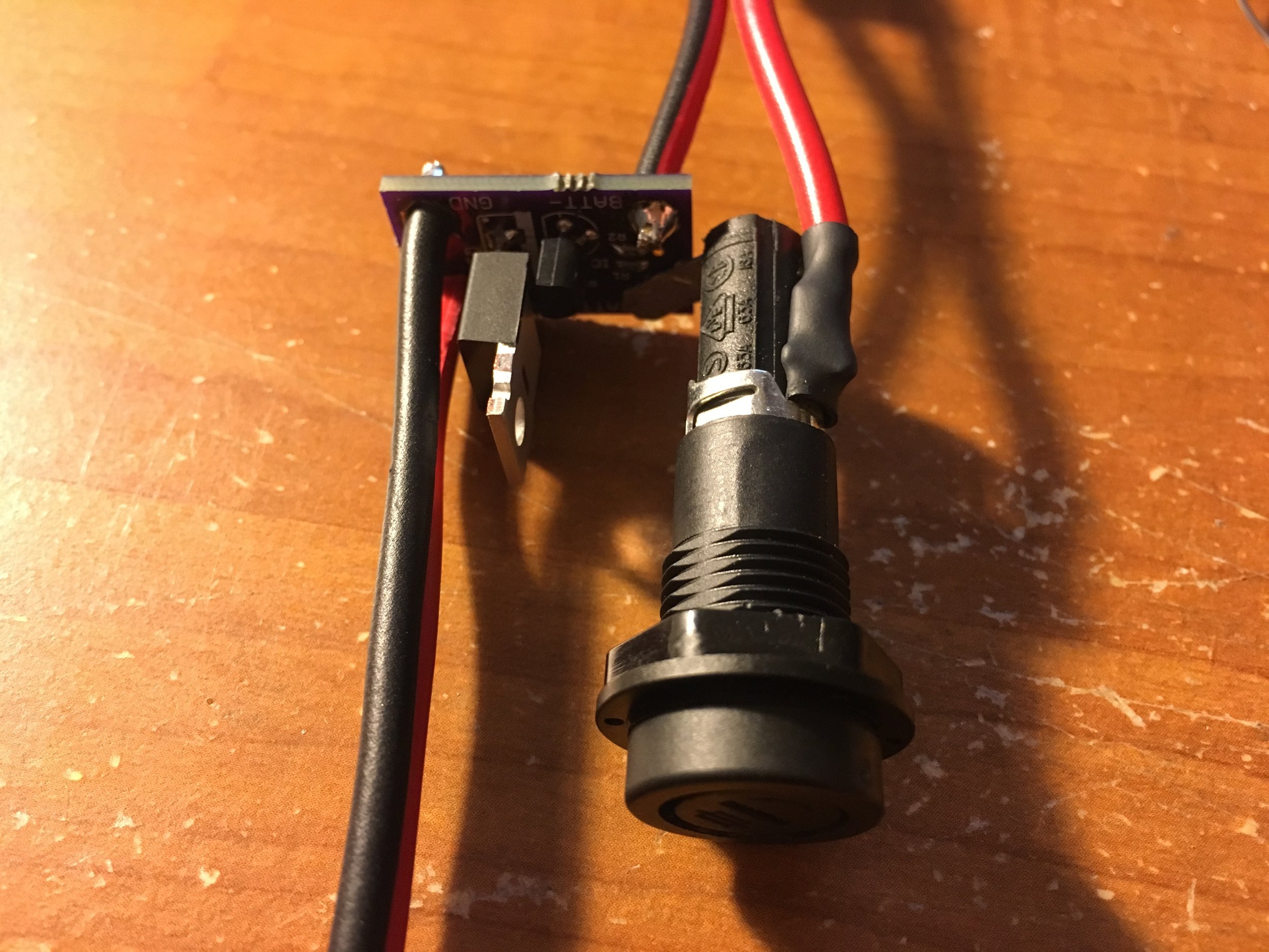
Luckily it was easy to solder on a fuse holder. You really don't want LiPo batteries to short. Especially the size I'm using.

The 5V 30A voltage regulator needed some connectors.
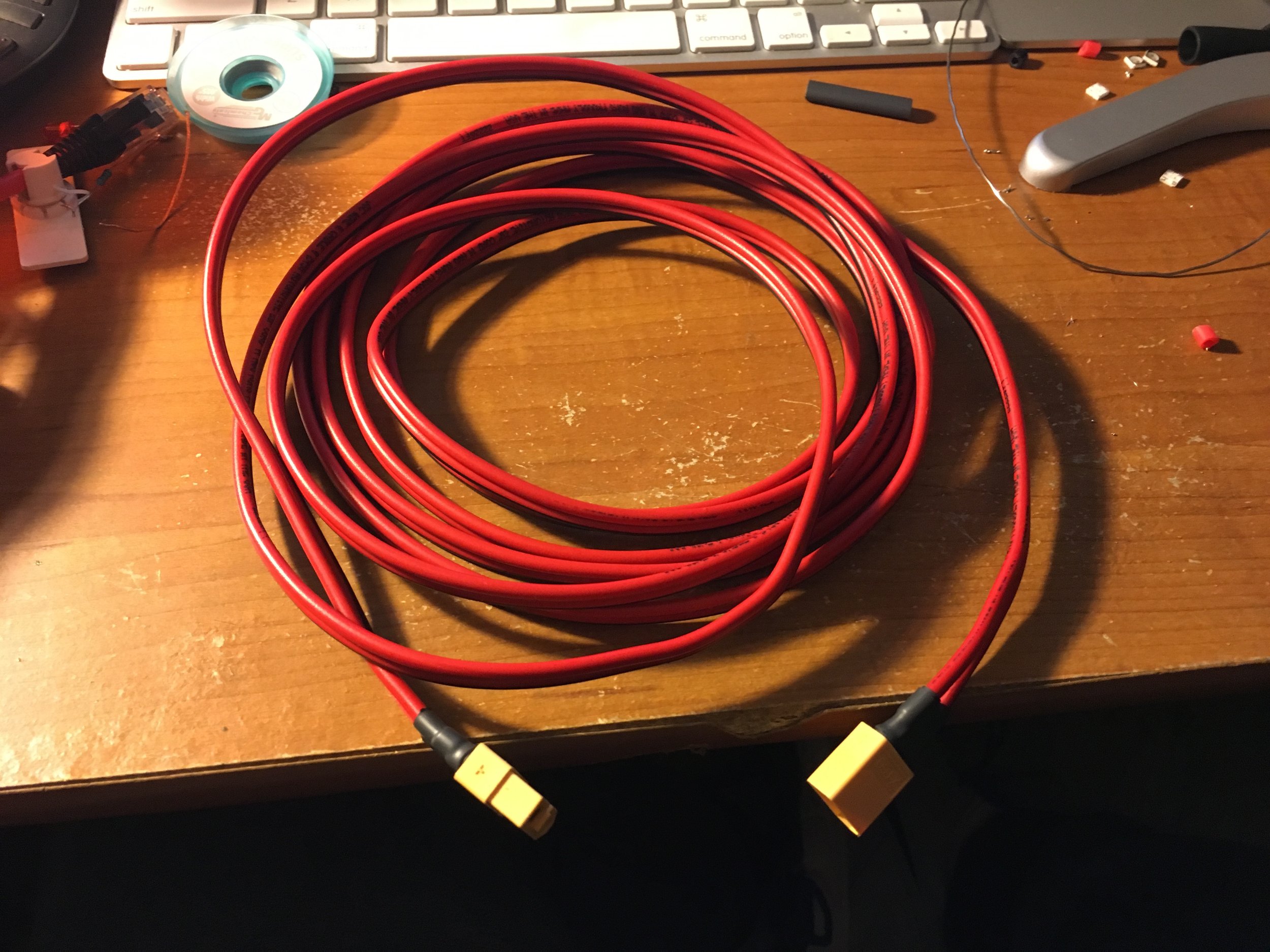
And I need an extension cord to run to my backpack (where I'm keeping the battery)

Speaking of the battery. This is what I'm using. I got 4 10,000 mAh 22.2V LiPo batteries. Each one should last me 5-6 hours depending on the animation, which should be good for two days or more of a festival.

I also had to switch out the connectors on these guys. Doing this made me really nervous. One mistake and I could end up with a MASSIVE fire on my hands.

Here's the power system all wired up and showing a steady 5V! Note that I got a LiPo safe so that should something go terribly wrong, the LiPo fire will be somewhat contained...

I 3D printed an enclosure to hold the low voltage cutoff board and added a power status LED. I can also hold one additional fuse.

Here's the LVC board all closed up and powered!
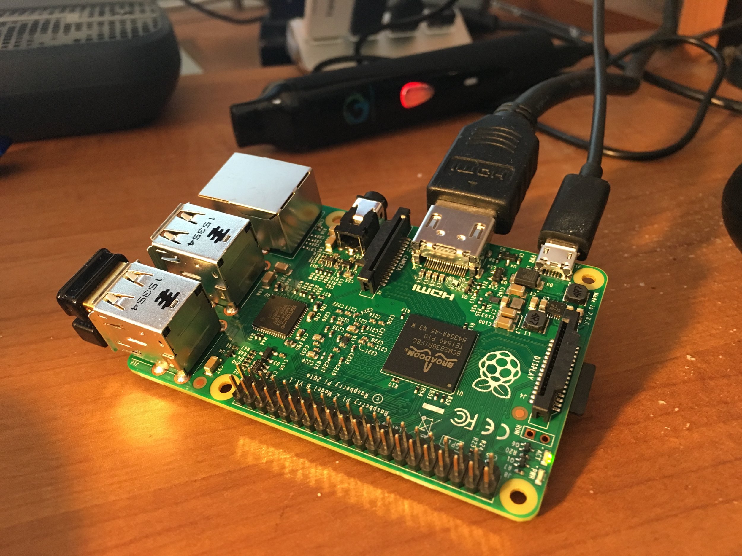
Originally I wanted to use a Raspberry Pi. This would allow me to use processing for the animations, and easily input adjustments in real time using a little bluetooth keyboard. Unfortunately the WS2812 LEDs require pretty precise timing that is hard to achieve on a microprocessor that's also running an operating system. I found a library that supposedly worked but I just couldn't get it running.
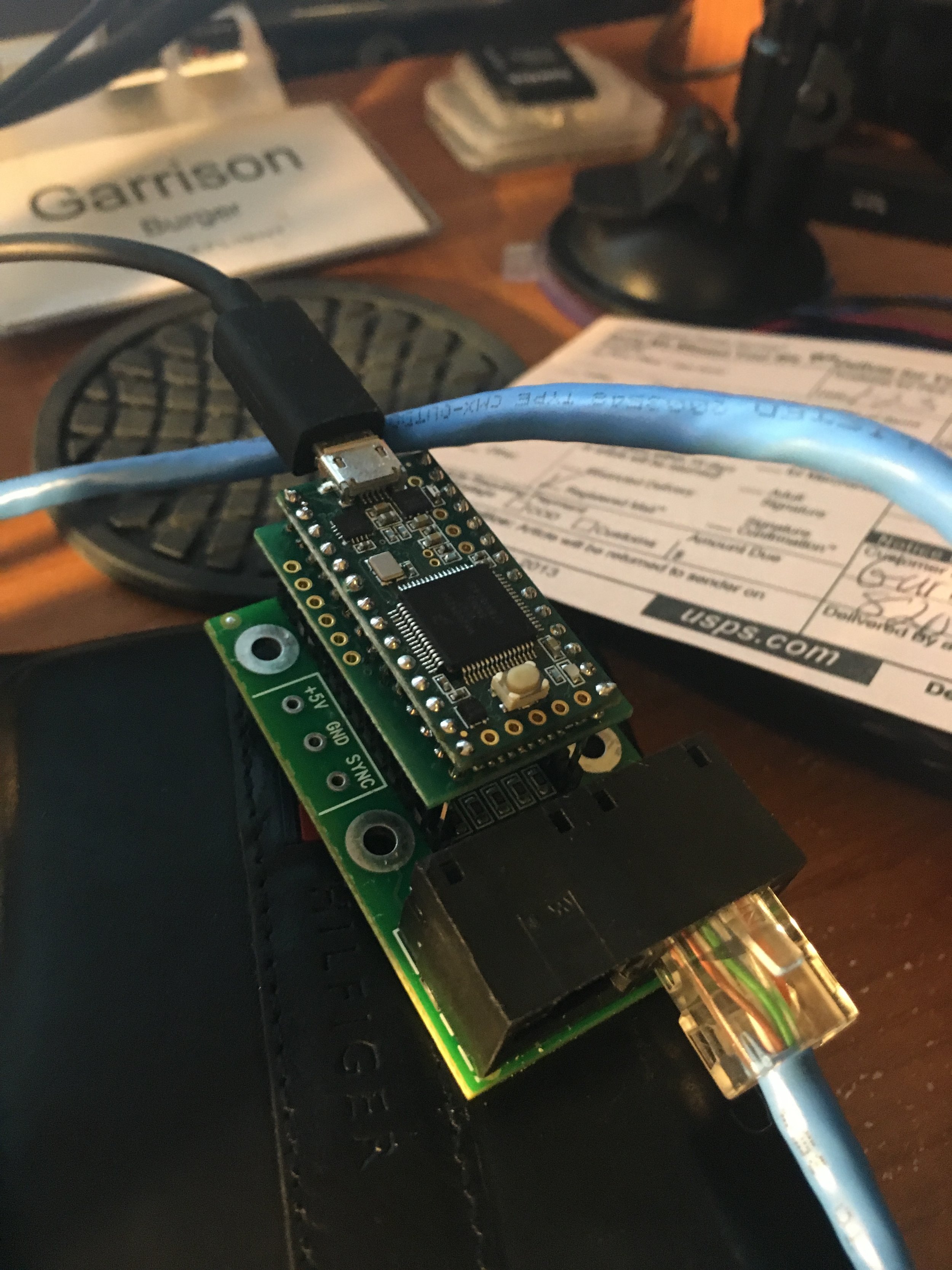
So after some more research into what people use to drive large LED displays, I came across the Teensy. It runs on the same code as arduino (which I already knew how to use) and is way more powerful. They also sell a shield called the OctoWS2811 which comes with a library for controlling the LEDs and I found examples of people controlling way more LEDs than I needed.
My first test was using some spare individual LEDs I had sitting around from an old project.
I then upgraded to a strip I got from Ali Express. It was at this point that I realized just how bright this thing was going to be.

Finally the second batch of boards arrived! It took a lot of searching but I went with Seeed Studio. They're based in China but their prices were really good. I read some concerns about the quality of the boards but I figured my circuits were so simple I didn't have much to worry about.

I got the entire order of 225 boards for $350 (including shipping) which was way better than I had expected to get. I even splurged and got ENIG finish and black solder mask.

And the quality turned out great!
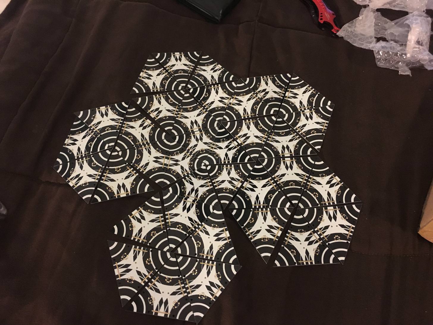
And the silk screen pattern is much more enjoyable this time around.
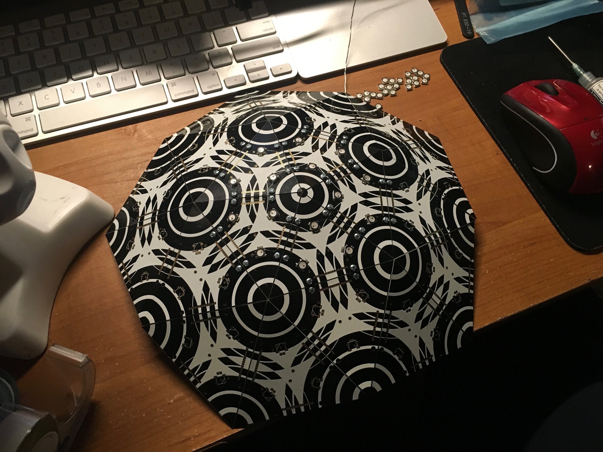
I got the LED footprints right this time and the LEDs lit up on the first try!
With the first panel together I'm starting to get really excited about how this is gonna look.

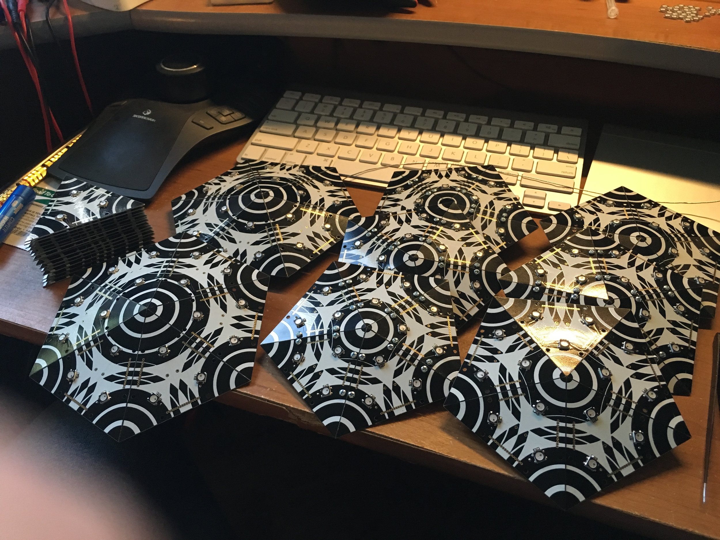
I 3d printed these brackets for the back side of each panel. It will connect to the fiberglass rods to get support from the core structure.
With the first panel together I can start to see how it's gonna look.
Here's a look at how the solder paste/hot air process works. It's way easier than soldering every pin by hand. Still tedious though. And I have 540 LEDs and 0603 capacitors to solder.
Unfortunately this process got the LEDs too hot, leading to premature failure and ultimately the construction of Version 2.
Got a good amount done on this weekend. Lots of time soldering and watching TV.

Here is the center hub. The fiberglass rods will fit over the nubs and the top and bottom halves can separate.

First two panels on the totem!

Joined by a third!
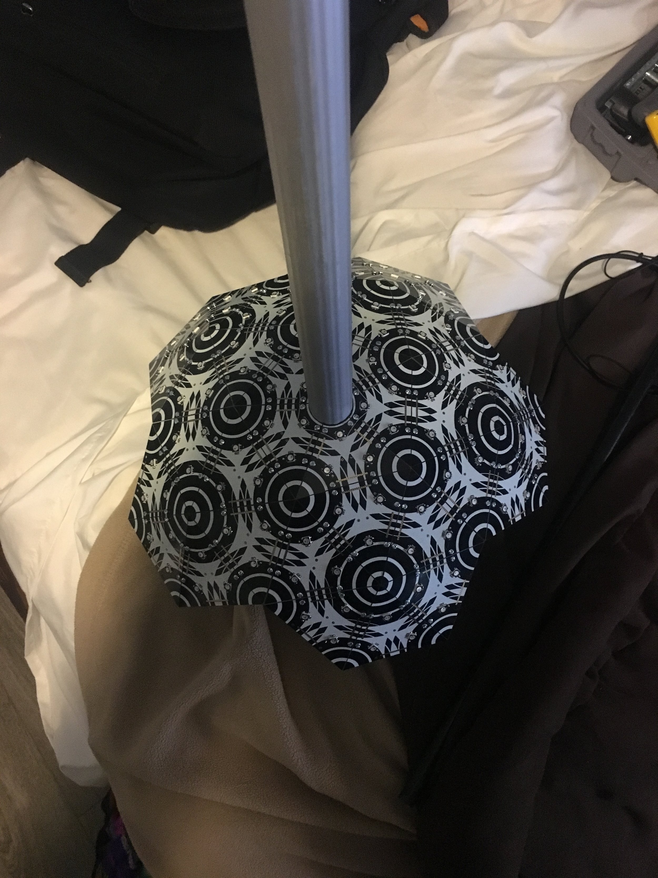

Kinda looks like a sea mine.
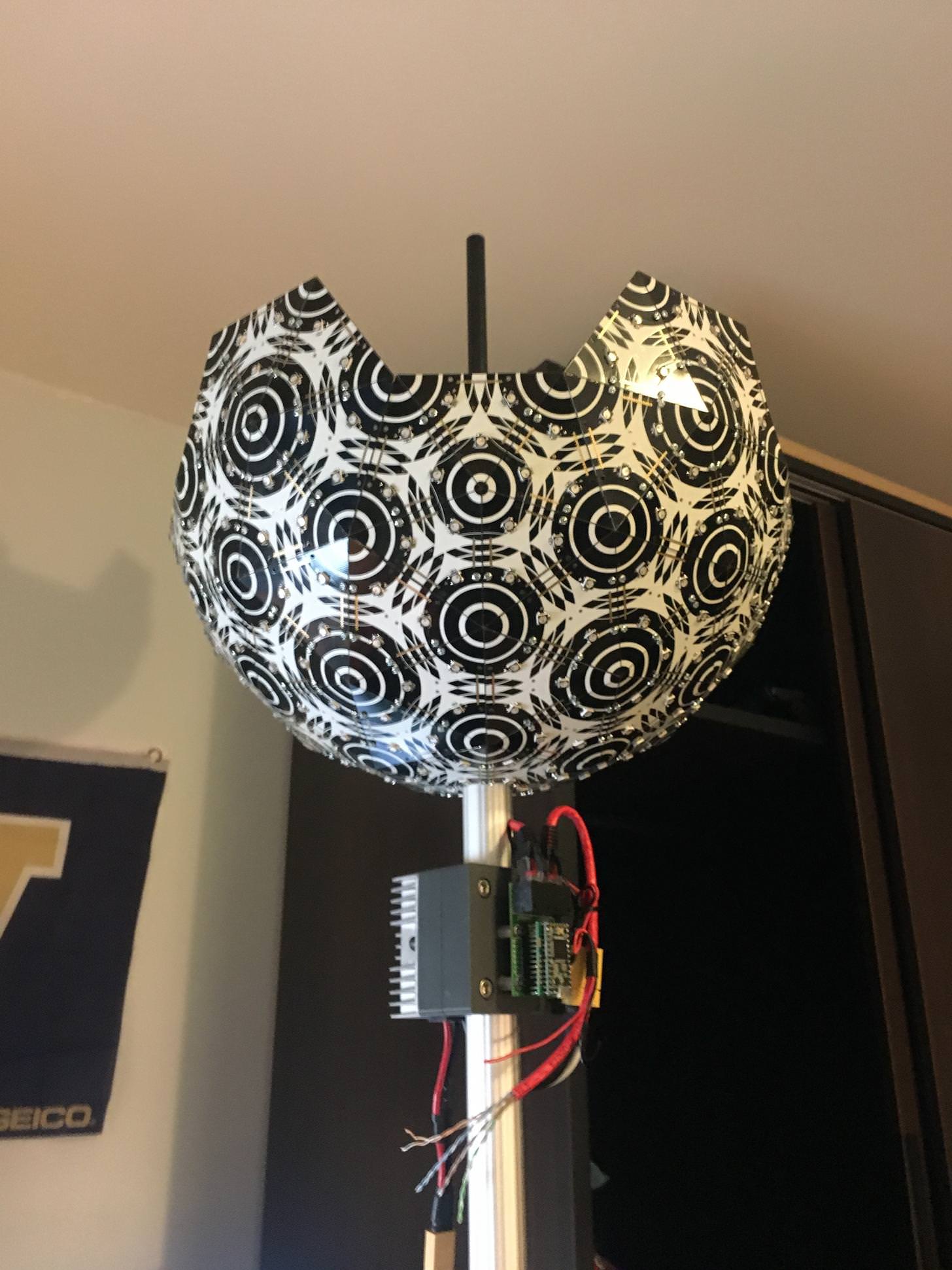
And the bottom half is done!
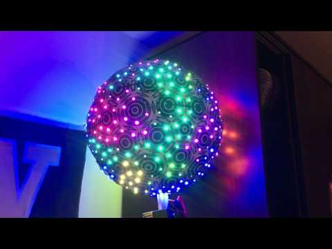
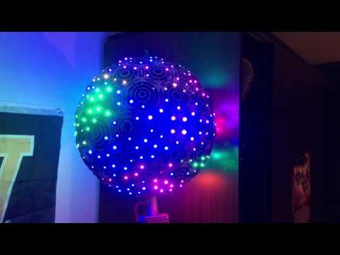
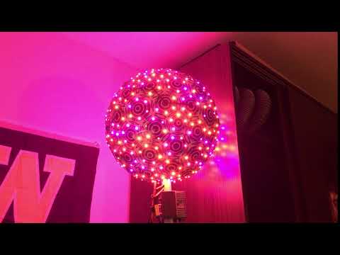
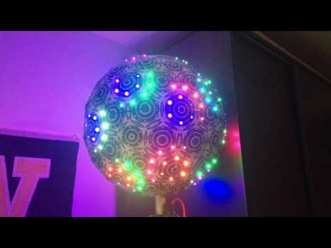
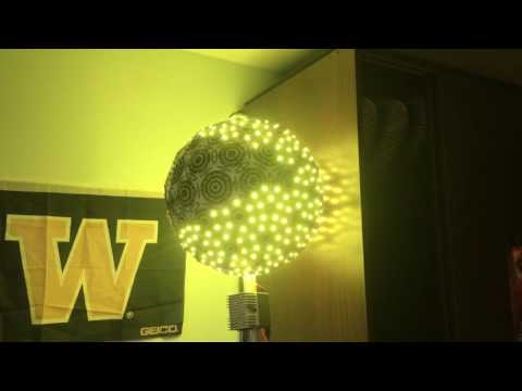
Time to fire it up! So pretty and bright

Even with only half of it done it lights up my room in the daytime.

After two Sundays of a solder party with my friend we had all the panels ready to finish the job!
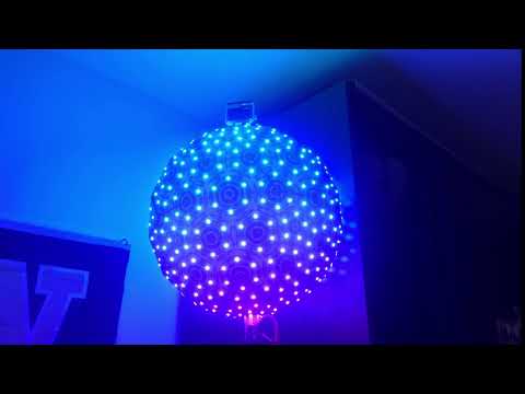
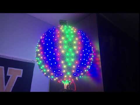
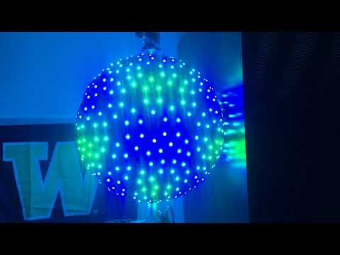
And here it is! First time firing it up I was so happy! I had spent a lot of money and 6 months on this project so far. So seeing it all together for the first time was wonderful.
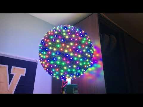
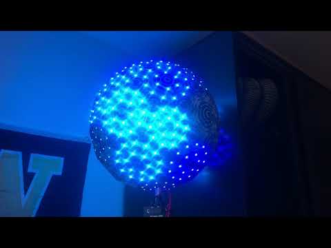
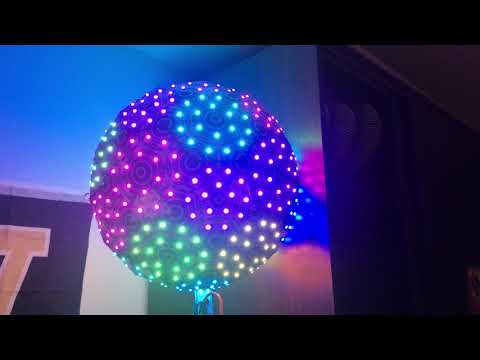
Animation Gallery