There were several issues with version 1 of SOL CRUSHER. Surface mount LEDs specify a certain temperature profile to use while soldering. The data sheet gives a specific rate of temperature increase, max temp, hold time, and cool down rate. This is typically achieved by a precision reflow oven, and my hot air process was primitive by comparison. This meant that LEDs were getting slightly damaged by my process and would soon start to fail (they should last thousands of hours when handled correctly).
Additionally, because the LEDs were set up in 4 "strings", a single failure could make up to a quarter of the ball completely glitch out and ruin the animations. Within hours of a festival, the totem would be a sparkly, glitchy mess and not the nice clean animations I wanted. I would end up replacing 20-30 LEDs between each festival, and using the hot air to rework them would thermally damage the nearby LEDs, furthering the problem. This was a never-ending cycle and the only solution was to replace every LED and use a normal soldering iron rather than the hot air gun. I figured if I was going to do all that soldering anyways, I might as well design a new version and fix some other annoyances as well!
The main goals of V2 were to fix the dead LED problem, ensure that a single LED failure wouldn't take out more than a few LEDs, significantly reduce the weight of the totem, more modularity (so I can fix things if and when they break) and have the battery built in (being tethered to my backpack was annoying and made it difficult to pass off to friends).

The basic geometry of the totem would remain the same: a geodesic sphere made from pentagons and hexagons, which are in turn built from 2 sizes of triangular circuit boards. Pentagons are built from AAB triangles and hexagons from CCB triangles. I would need 60 AAB circuit boards and 120 CCB boards. I calculated the lengths for my desired size using this tool.

This is the model of the AAB board. To cut down on weight I made large cutouts in the boards leaving just enough space to route the power and data lines. This would also pattern to make a cool design instead of the silkscreen pattern I used last time. Instead of attaching to each other by a long solder joint on every edge, only the small "ears" would be connected. To save on weight I also decided to use 0.5mm thick PCBs. I was a bit concerned about the how strong this would all be, but the first version was way overbuilt. The thick boards and large solder joints along every edge made it nearly indestructible, so there was a lot that could be cut back.
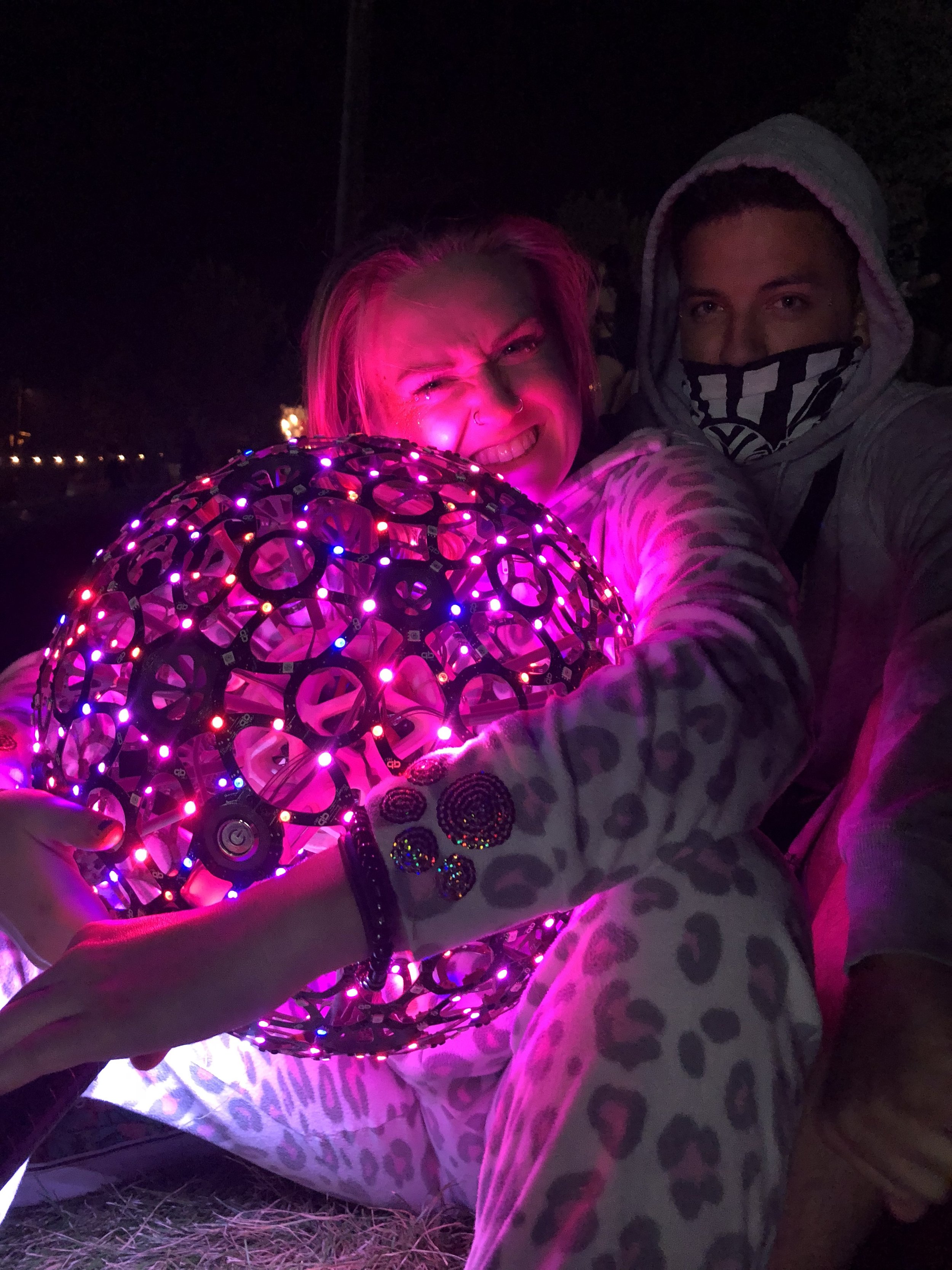
I also put an additional LED on the back side of each board, to illuminate the now visible internal structure of the totem. This increased the total LED count from 540 to 720.
For this totem I also made the switch from WS2812 LEDs to APA102. These LEDs have a data and clock line and communicate over SPI. While this means I have an additional signal to route around, the strict timing requirements of the WS chips are removed and I can write the LED data a lot faster. I'm not a strong programmer so my inefficient code can use all the help it can get in having more time for calculating animations and less time sending data to the LEDs.

This is the circuit layout of the AAB board. Power and ground are connected to the adjacent boards through the "ears" at the top of the board. The clock and data signals are connected through the bottom "ears".
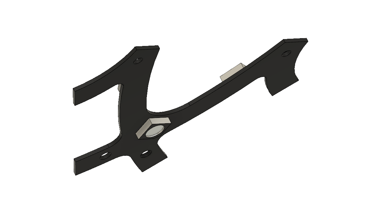
This is the support structure for the pentagon panels. I made these a lot smaller this time, only holding on to the top part of each panel.
This time around I used Fusion 360 to model things. This software is free to use for makers and small businesses. While it has a bit of a different workflow than other parametric CAD software, once I figured it out it proved to be a solid solution.
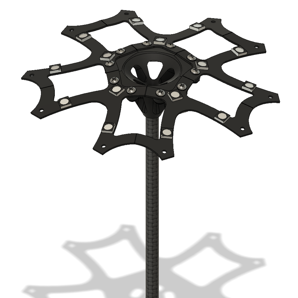
This is how the boards and support come together to form a pentagon panel. Each one of these will be connected to it's own data line from the Teensy microcontroller. This means a single LED failure will at most only remove a single panel of LEDs. In practice I've only seen at most 3 or 4 LEDs near the end of the chain glitch out, so even when a couple LEDs die, the animations still look great!

This is a hexagon panel built from CCB boards. It's put together in the same way as the pentagons.
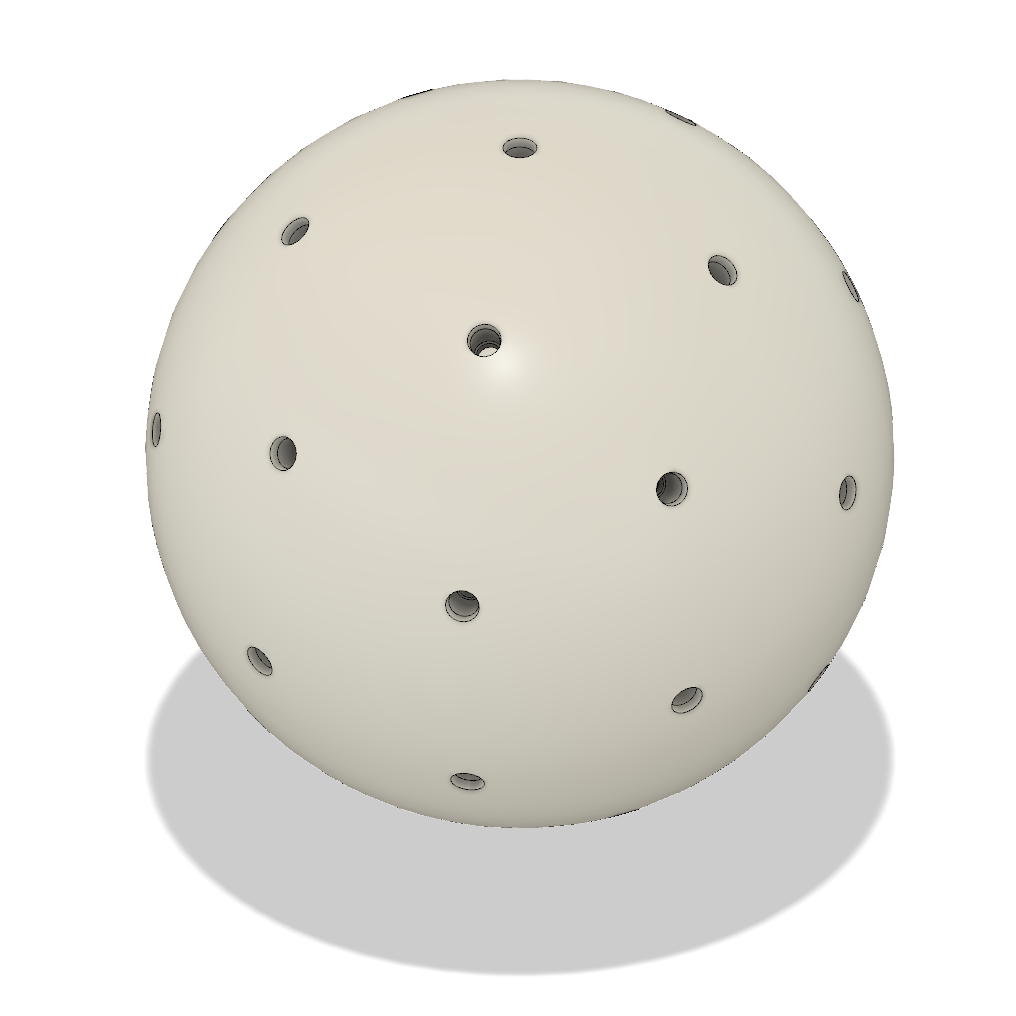
The design of the center hub to connect the panels to and house the power converters was tricky and really stressed the limits of Fusion 360. I started with a hollow sphere with a hole for each of the support rods.

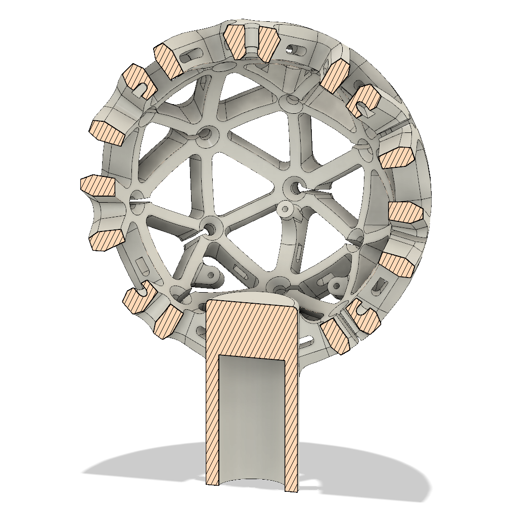
I then made several cutouts to reduce the amount of material used and lighten the ball.

The cutouts were then mirrored and rotated copied to complete the lightened structure. The little slots were to pass wires through since I originally was planning on using carbon fiber rods and passing the wires through the center. These proved to be too weak and I switched to wooden dowels so the slots were not used.

I also added some small cutouts in each of the beams to zip tie the wires in place and keep things tidy.
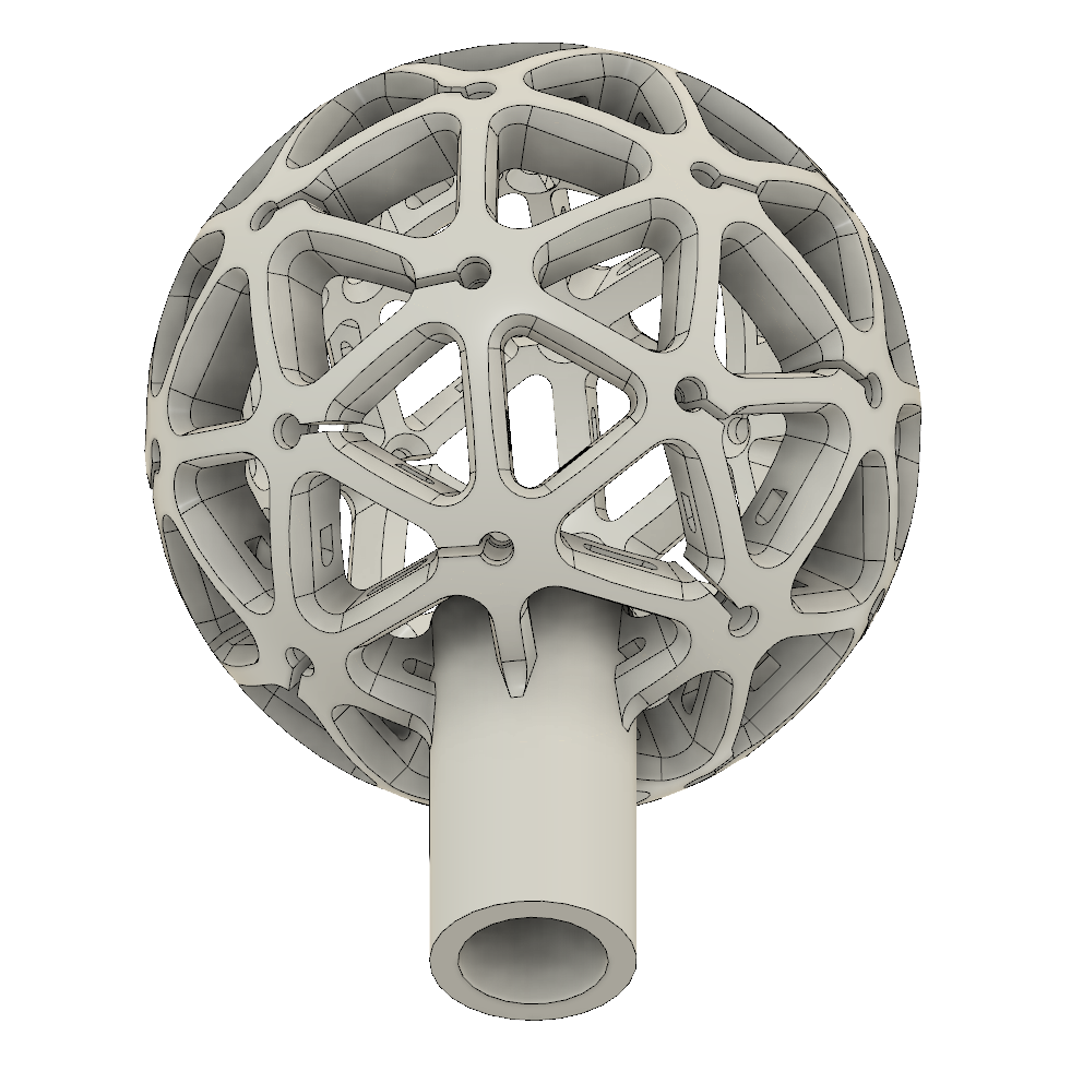
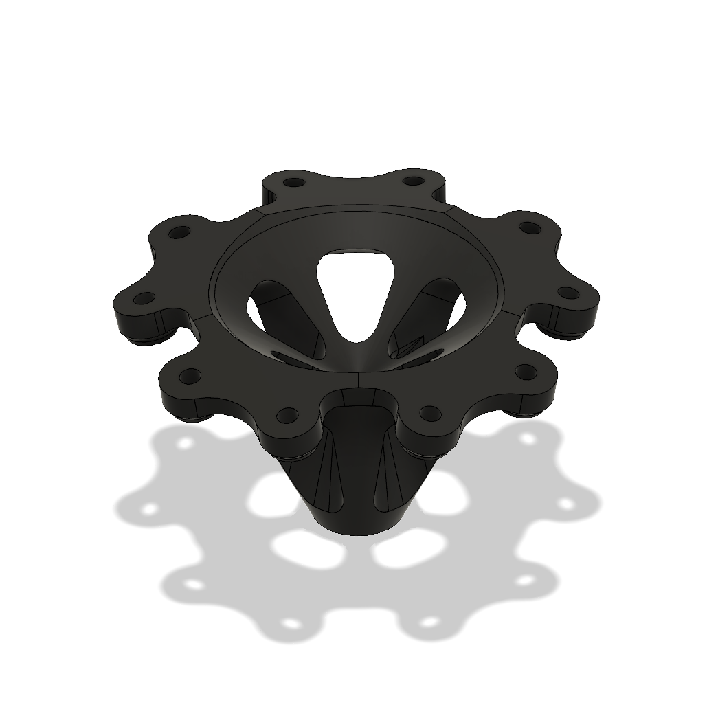
To connect to the pole (same pool skimmer pole as last time) I extruded a cylinder out the bottom and blended it into the hub.
I then added some mounting locations for the circuit board.

Then I cut the sphere in half and added some points where it could connect back together with some set screws. This allows the top and bottom half of the totem to be separated to get me access to the insides.

The bottom then needed to be extended to provide a mounting location for the bottom pentagon. The two little nubs are for set screws that will lock the totem to the pole.

A few more parts were designed to have a method for the pole to plug into the hub to provide power to the system.

And with that I could assemble the whole thing and start to see how it would look. At this point I was getting really excited at how this was coming together.
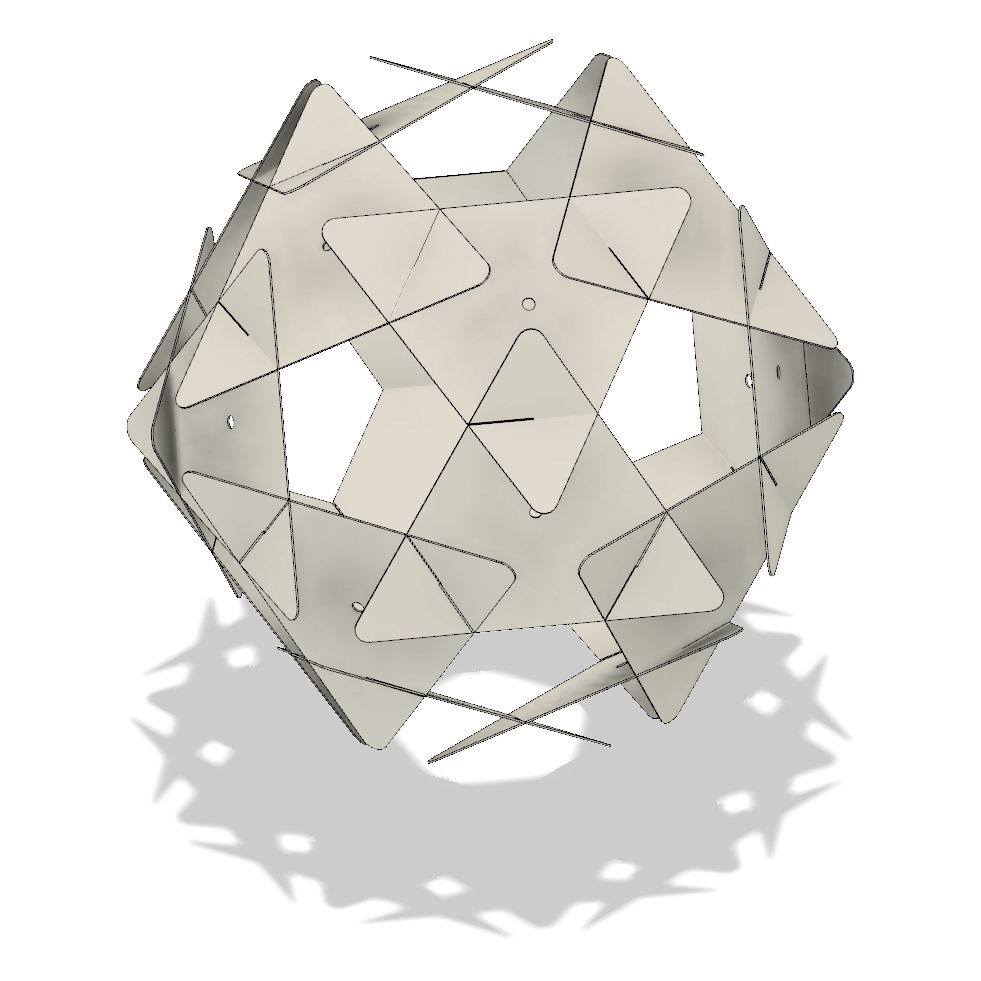
At some point I want to add some plastic panels to the inside to catch the light of the internal LEDs but I haven't gotten around to this yet.

Once again I ordered the PCBs from Seeed Studio. They've got the best deals I could find to get several hundred boards made.

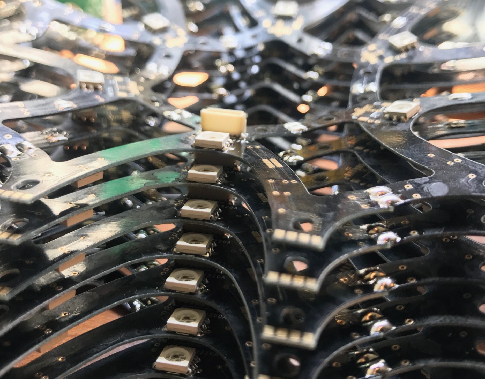
They came out really nice. The 0.5mm thickness seemed really thin but I knew it would be saving me a lot of weight.

I started the long process of soldering every LED by hand. Not using the hot air gun made this slower, but with the proper application of some flux and lots of practice this got easier and faster.
Thankfully the APA102 chips don't need a capacitor for every LED so that made it a bit simpler than last time. Once again I binge watched a lot of TV at my desk while doing all these.

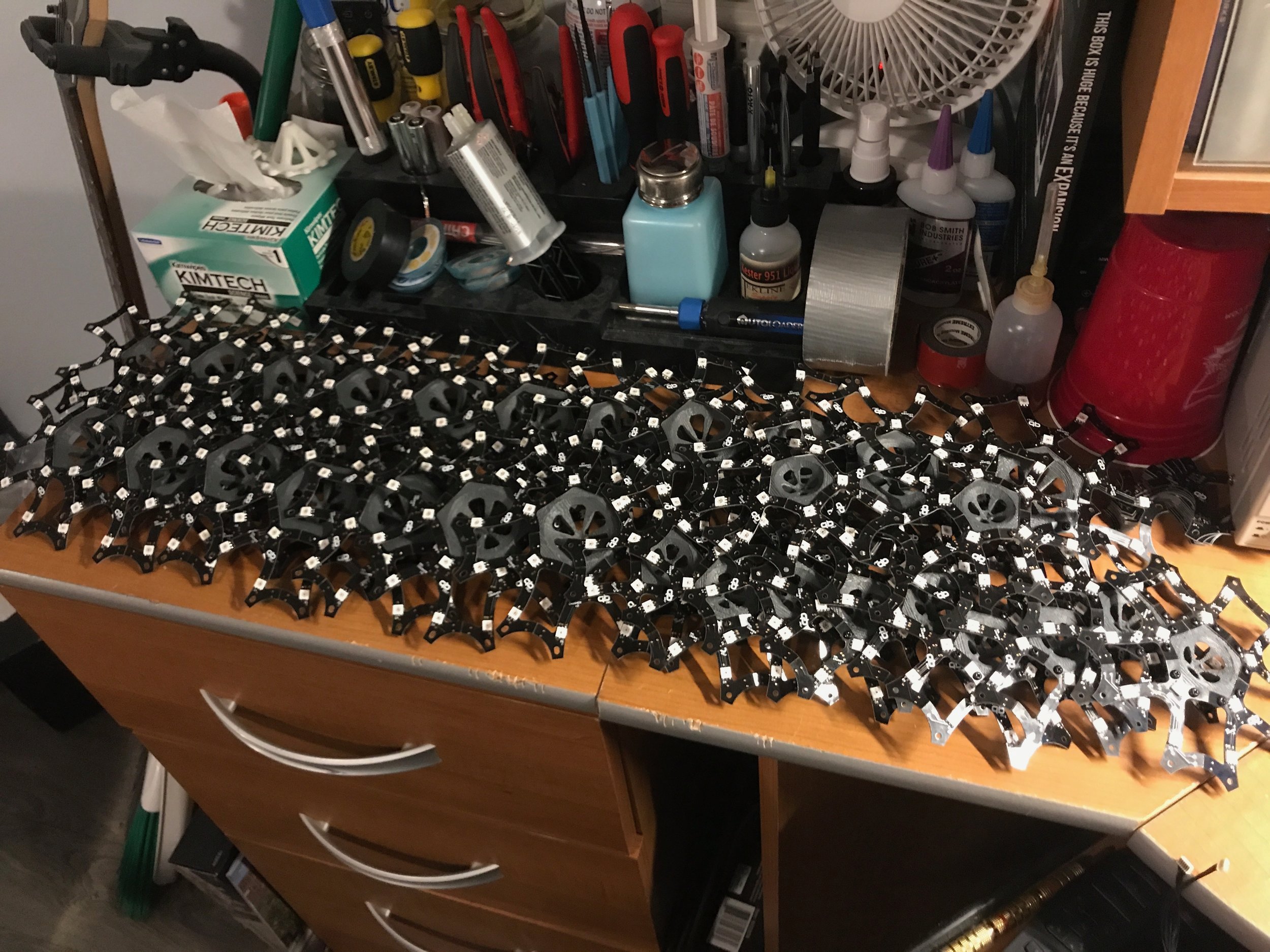
Finally done... Now to put them all together...

I could use the 3D printed supports to hold the circuit boards at the correct angles while soldering them together. This was much simpler than the jigs I made the last time for a similar purpose. You can see scorch marks from where the soldering iron was getting close to the plastic.

I decided to use these tiny little JST SR connectors to get the power and data to each panel. With pins only 1mm apart, they were a total pain to solder, but they ended up working great and fit nicely on the back of the panels.
Here you can see the connectors have been added to the panels.

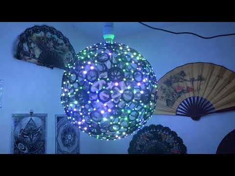
With the connectors in place I could hook up a few of the panels and see how they looked! I really like how the backside LEDs give a glow behind them. It really adds a lot of depth.
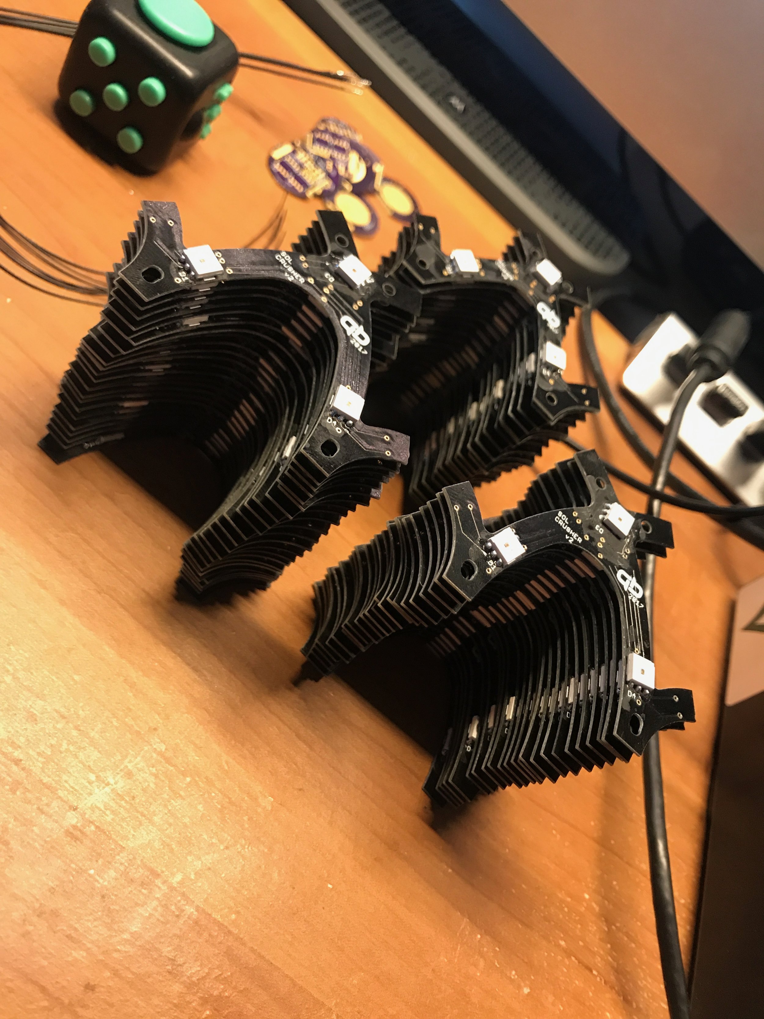
All the panels are finished and attached to their support brackets!


To protect the boards from any potential water damage I gave them all a healthy dose of conformal coating.
To build the battery pack I needed a way to spot weld nickel strips to the ends of the cells. This process is used in building battery packs because soldering the tabs would put too much heat into the cells and potentially damage them. I built the spot welder following the plans found here.
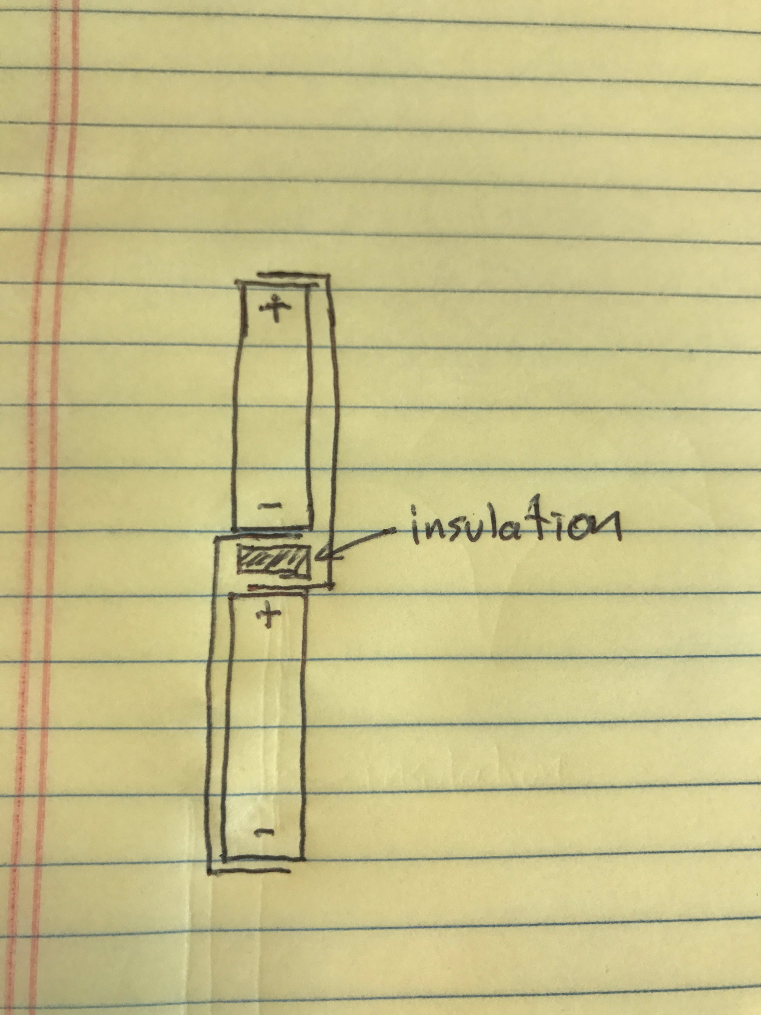
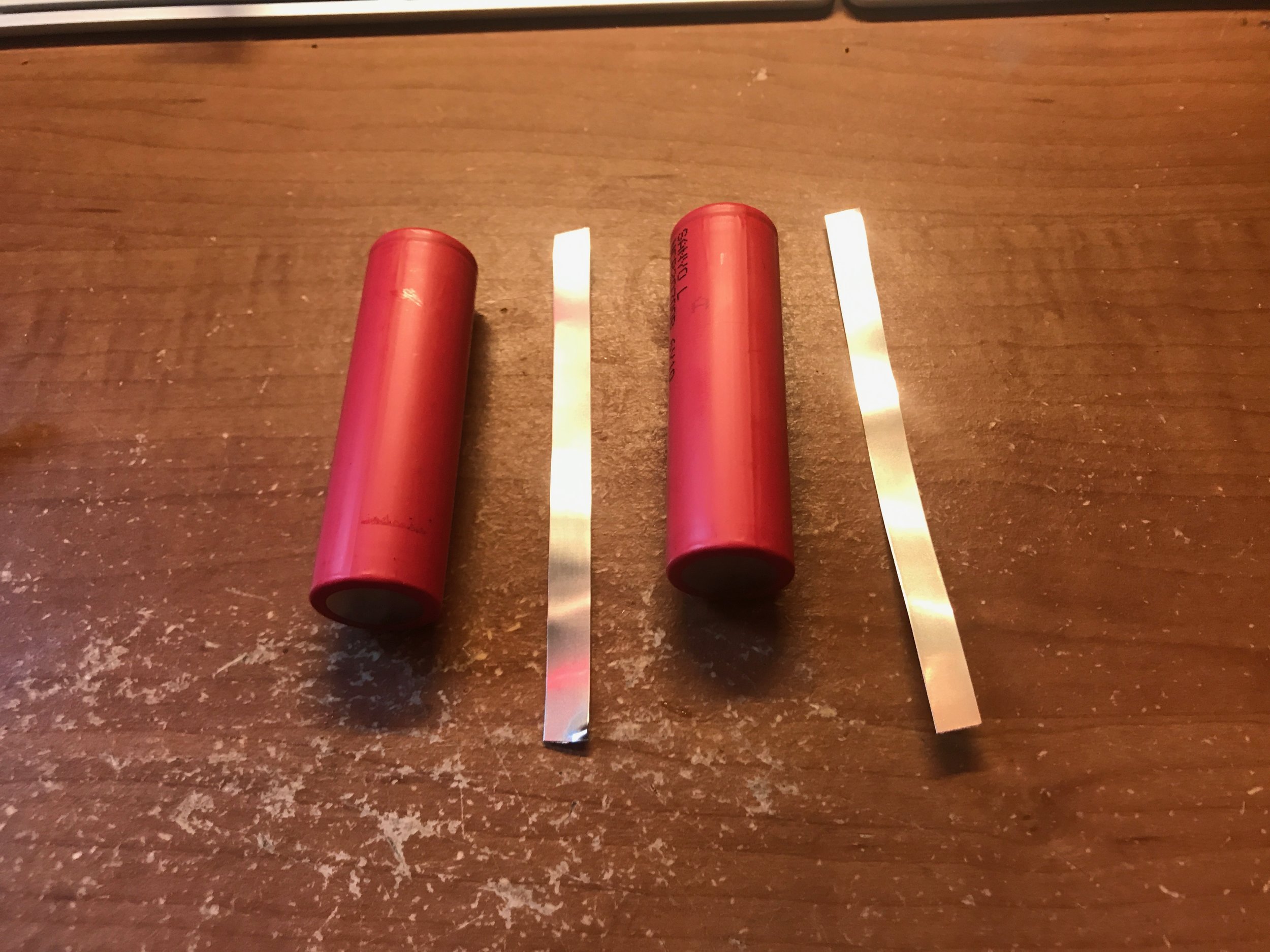
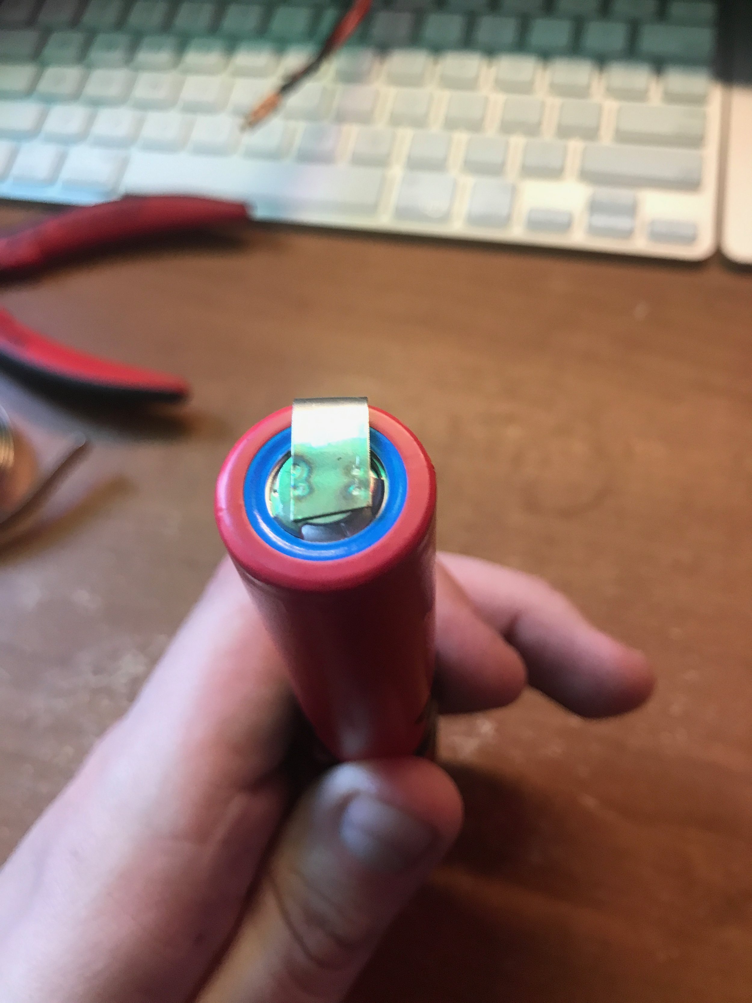
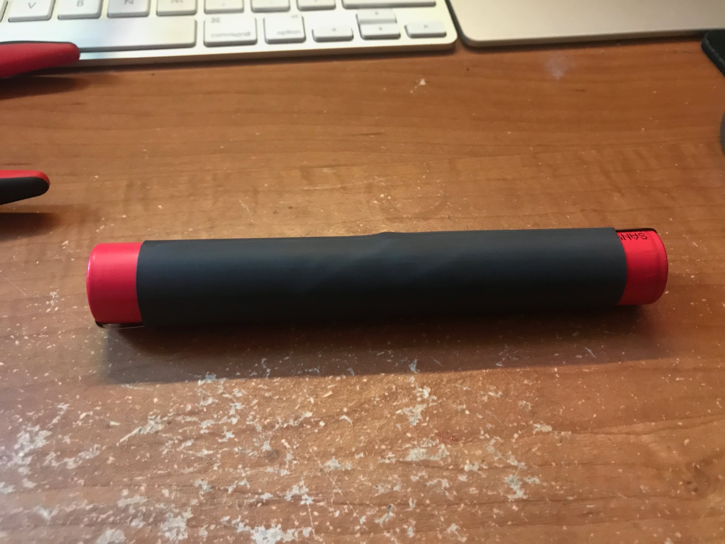
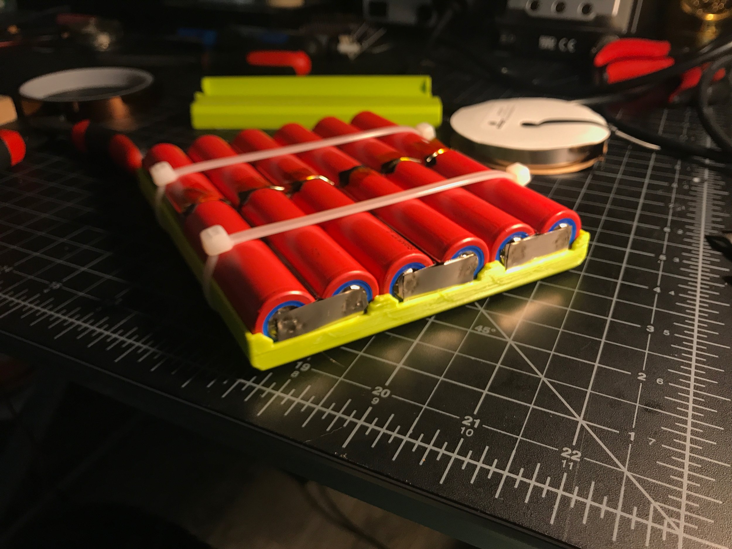
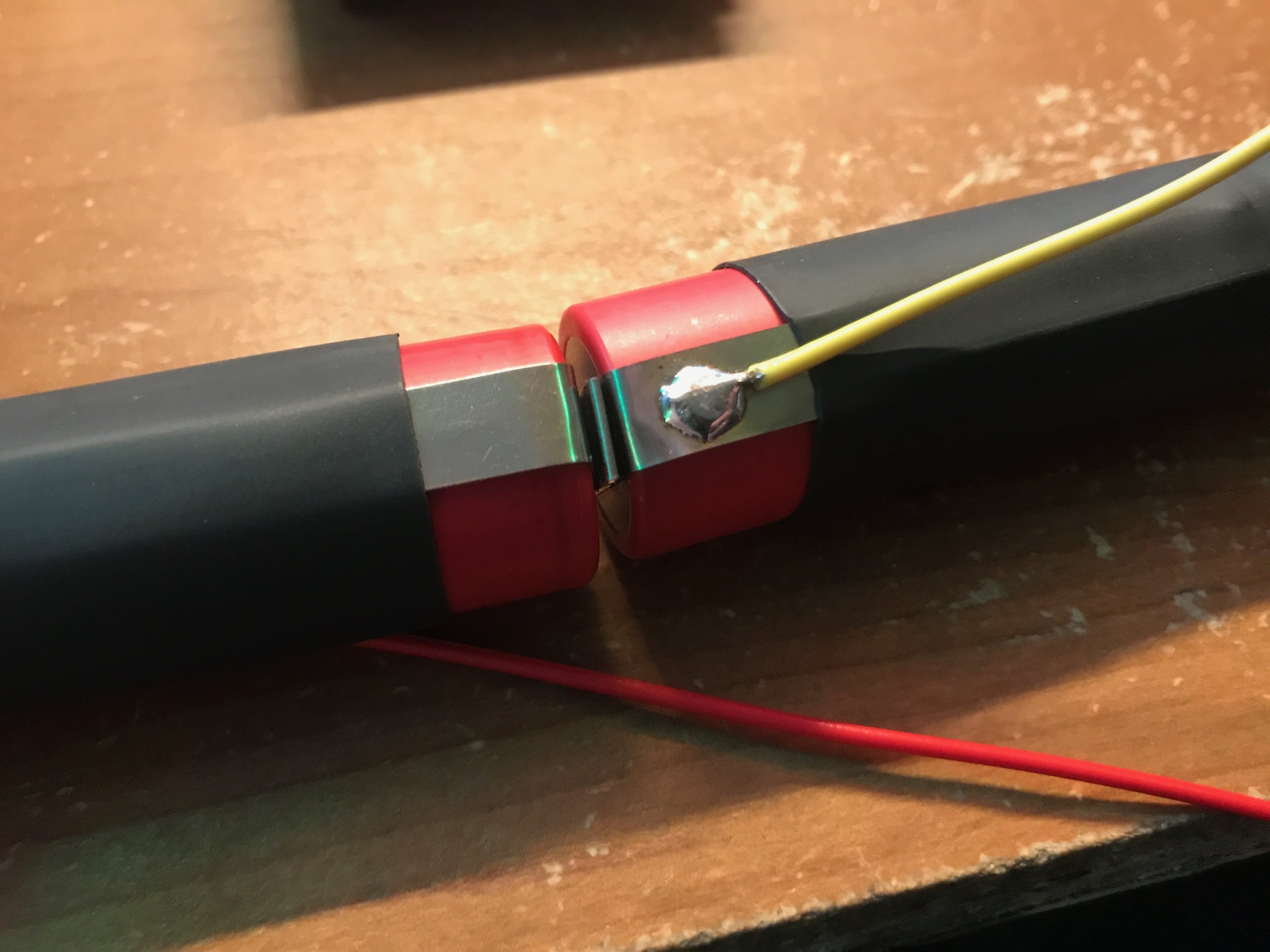
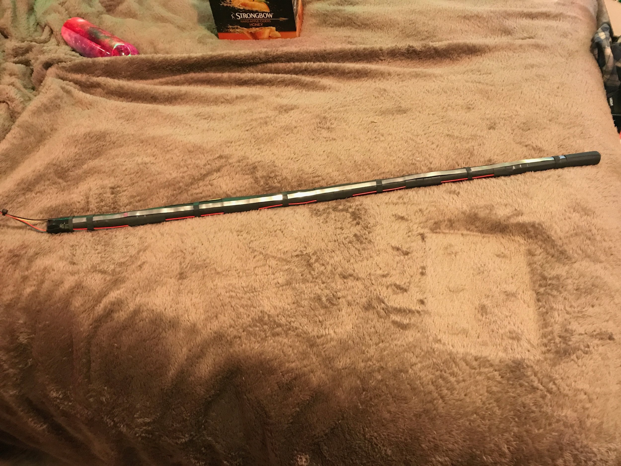
To power the totem I needed a solution that could be mounted within the pole. The pole's inside diameter is 23mm. 18650 cells (used for ecigs) would fit, but the new 21700 size (used by Tesla's Model 3) would be slightly larger while still fitting in the pole and have more capacity. I found Panasonic-Sanyo NCR20700B 4250mAh cells for $9 each. Six cells in series gives a 22.2V battery (same as version 1). To get more capacity, 12 cells with parallel pairs would be ideal (Giving a 22.2V 8500mAh battery pack). However, connecting end-to-end cells in parallel was tricky to figure out. The images above show my solution and the process of putting together the pack.

To convert the 22.2V from the battery to the 5V needed by the LEDs, I found these small board mounted DC-DC converters. They are part of a board mounted converter standard used by the telecommunications industry. This is an 1/8th brick size converter, and measures 2.30" x 0.90" while outputting 120W (24A). Two of these (one for the top half and one for the bottom half) will be enough to power all LEDs at full brightness white, however this would be far too bright and might be too much for the converters to handle without additional cooling. This would also drain the battery in about an hour, so the LEDs will be nowhere near their full brightness.


Two of these boards hold the power converters, Teensy microcontroller (on only one board), and all the connectors to send signals to the panels. The row of pins at the bottom are for a ribbon cable to connect the boards together, sending data from the main board containing the Teensy to the secondary board that routes the signals to the top half of the totem.
The Teensy 3.2 has 34 digital pins to use. Since there are 32 panels, 32 signals are used for the data pins. However I need all the panels to share the same clock pin since I only have 2 to spare. Luckily this is trivial to do in code, however when I tried hooking things up, it simply wasn't working. It turns out the Teensy only has so much current it can output, and by splitting that current 32 ways, there wasn't enough power to trigger the clock pins on all the LEDs. The solution was a sort of repeater chip called a clock buffer that takes the clock input and outputs 10 identical clock signals. The two rectangular pads at the top of the board in the right picture are for the clock buffers.
This video shows the two boards connected by a ribbon cable each driving one panel. Both boards have their own power converter and the top board has the Teensy microcrontroller.
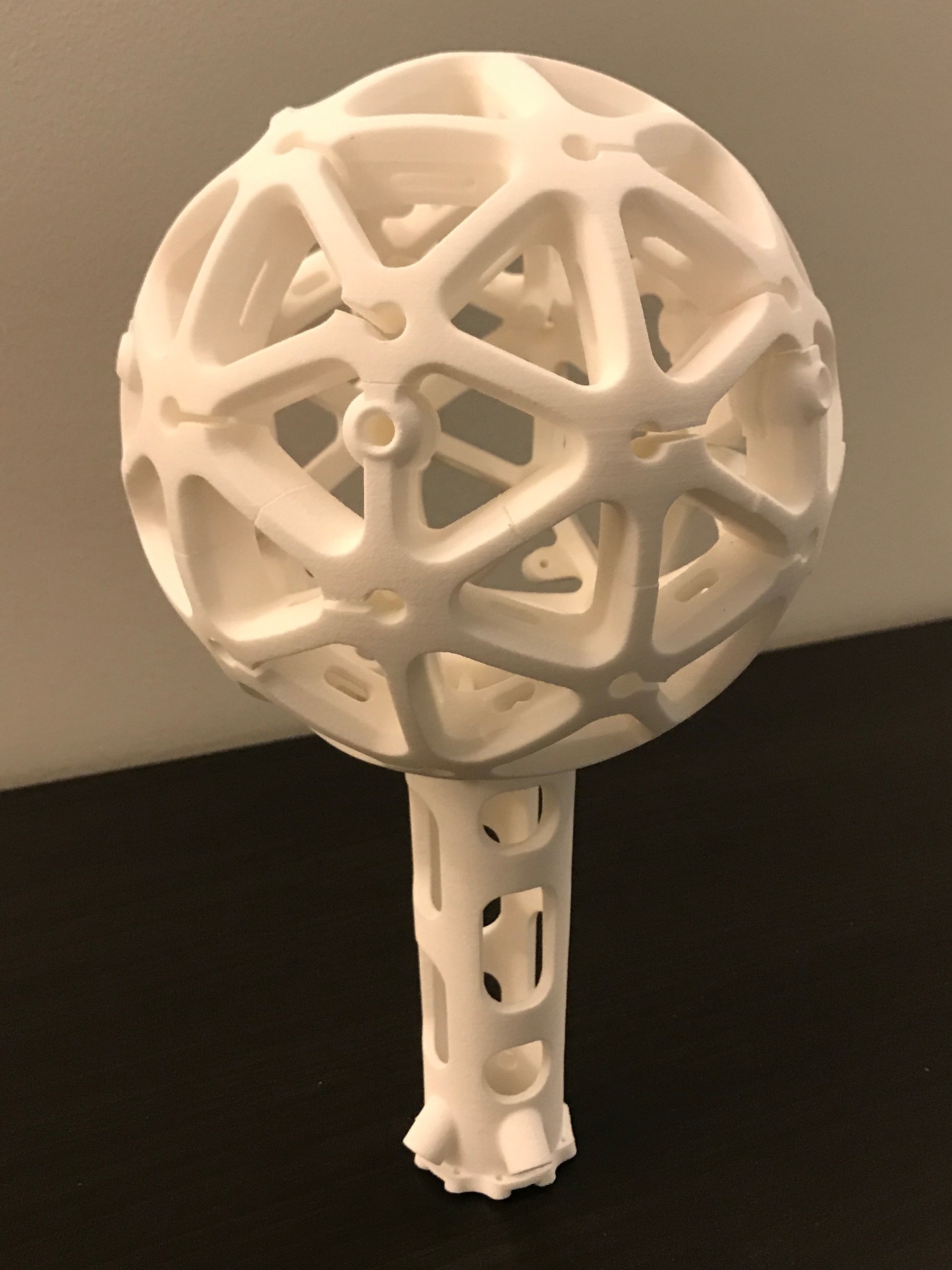
Since the hub was such a complicated part, I didn't really feel comfortable printing it myself. So I uploaded the design to Shapeways and had it printed in their "Strong and Flexible" materal. While expensive, the print came out absolutely flawless

Test fitting the bottom panel and pole. Everything is fitting together nicely.

Putting it all together and things are looking great.
With the first panels on the totem I could light things up for the first time.

Here the lower distributor board has been mounted in the hub and the panels have all been connected and the wires neatly tied up.
With the lower half of the totem wired up, I could really put things to a test. Only a few LEDs needed replacing, but all the panels were getting power and data correctly! (Apologies for the vertical Snapchat video).

The little brown ovals are small 3D printed brackets that are used to hold the panels together. In version 1 all the panels were soldered together so once it went together it was pretty much impossible to take apart. Attaching the panels with these brackets (and having them wired individually) means that if I need to replace an LED I simply remove some screws, unplug the wire and the panel comes right off.

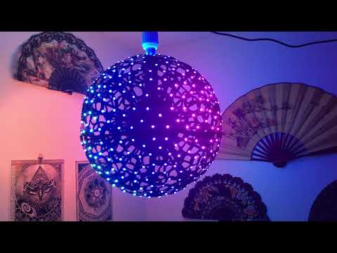
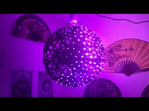
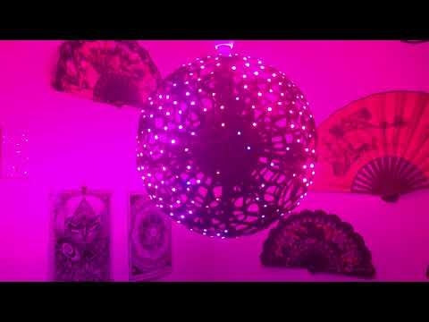
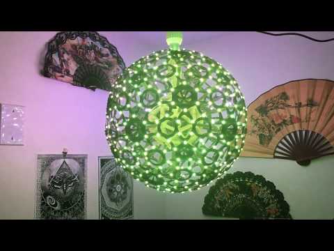
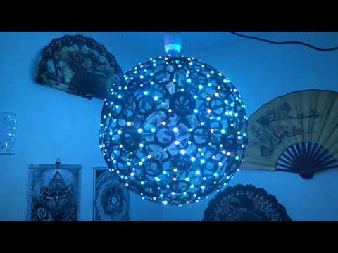
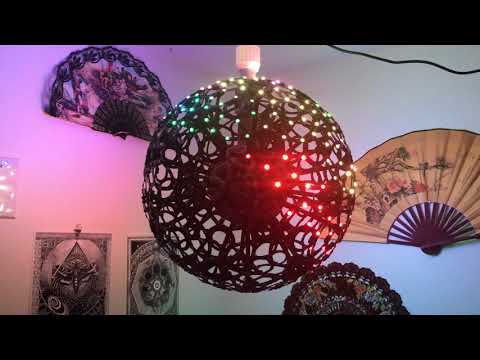
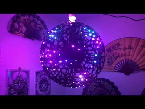
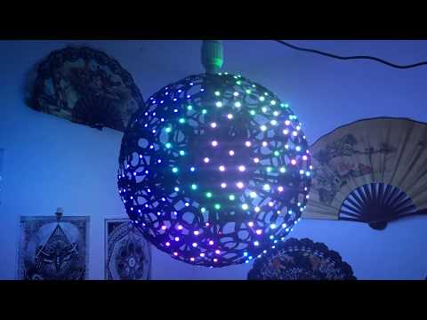
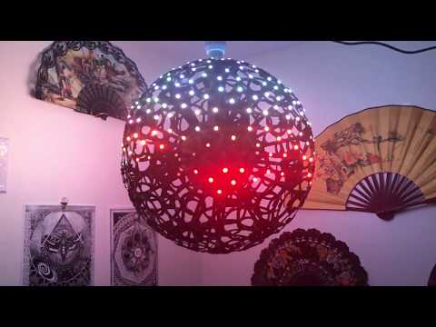
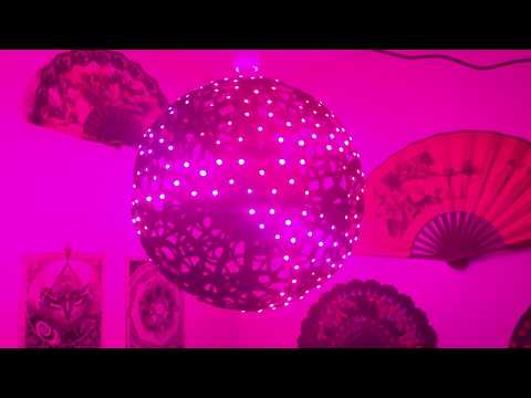
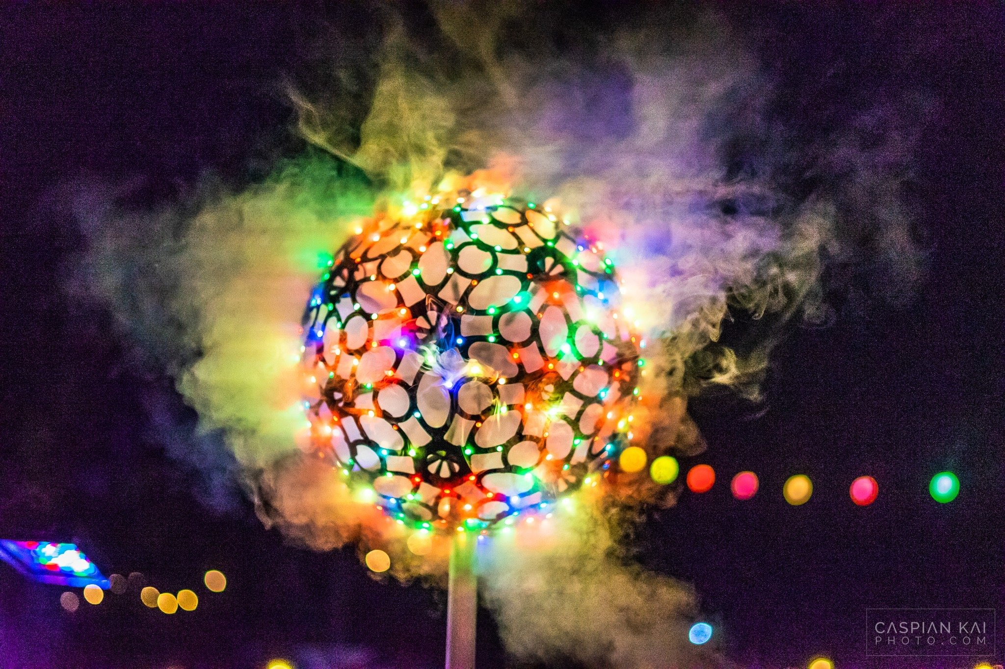
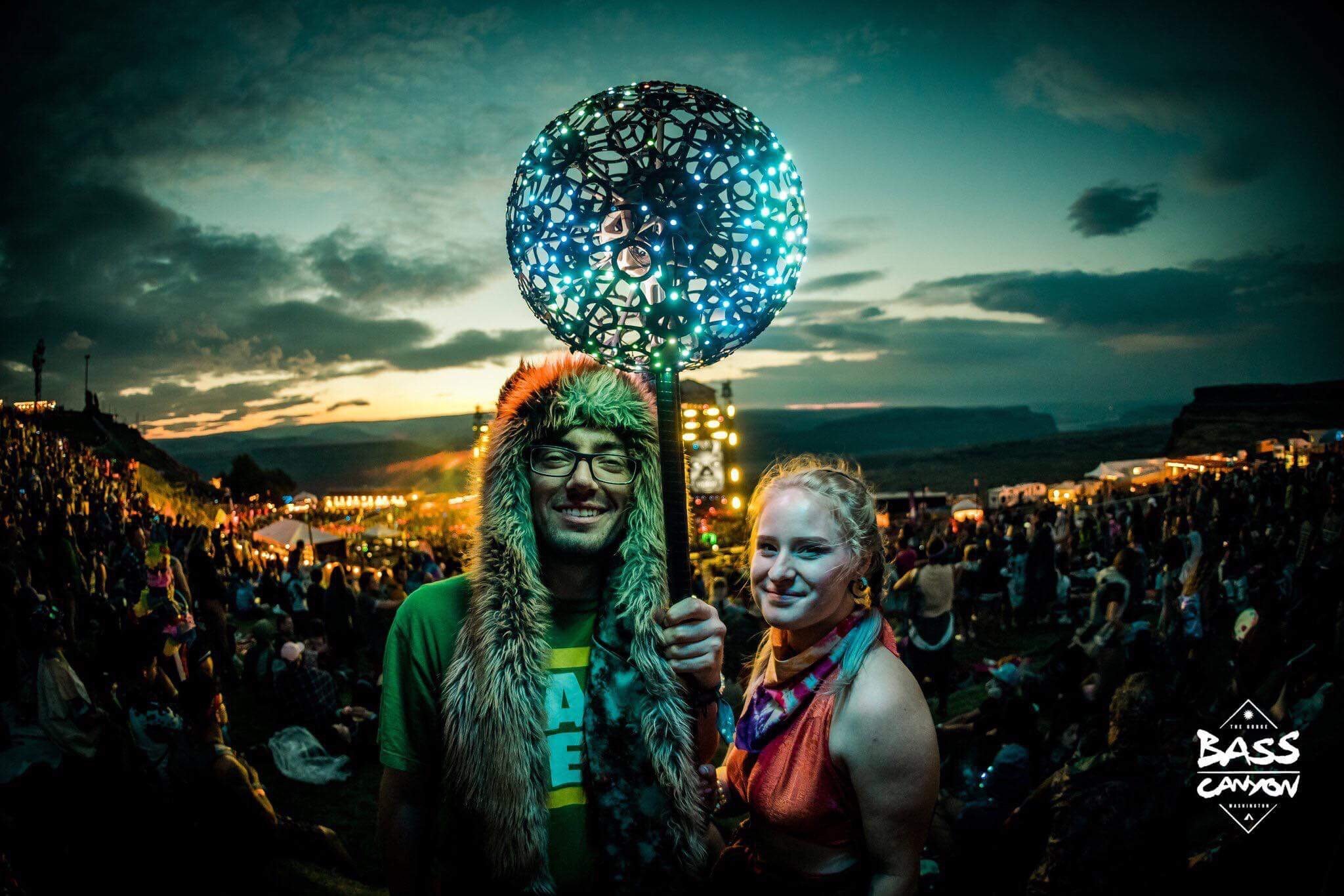
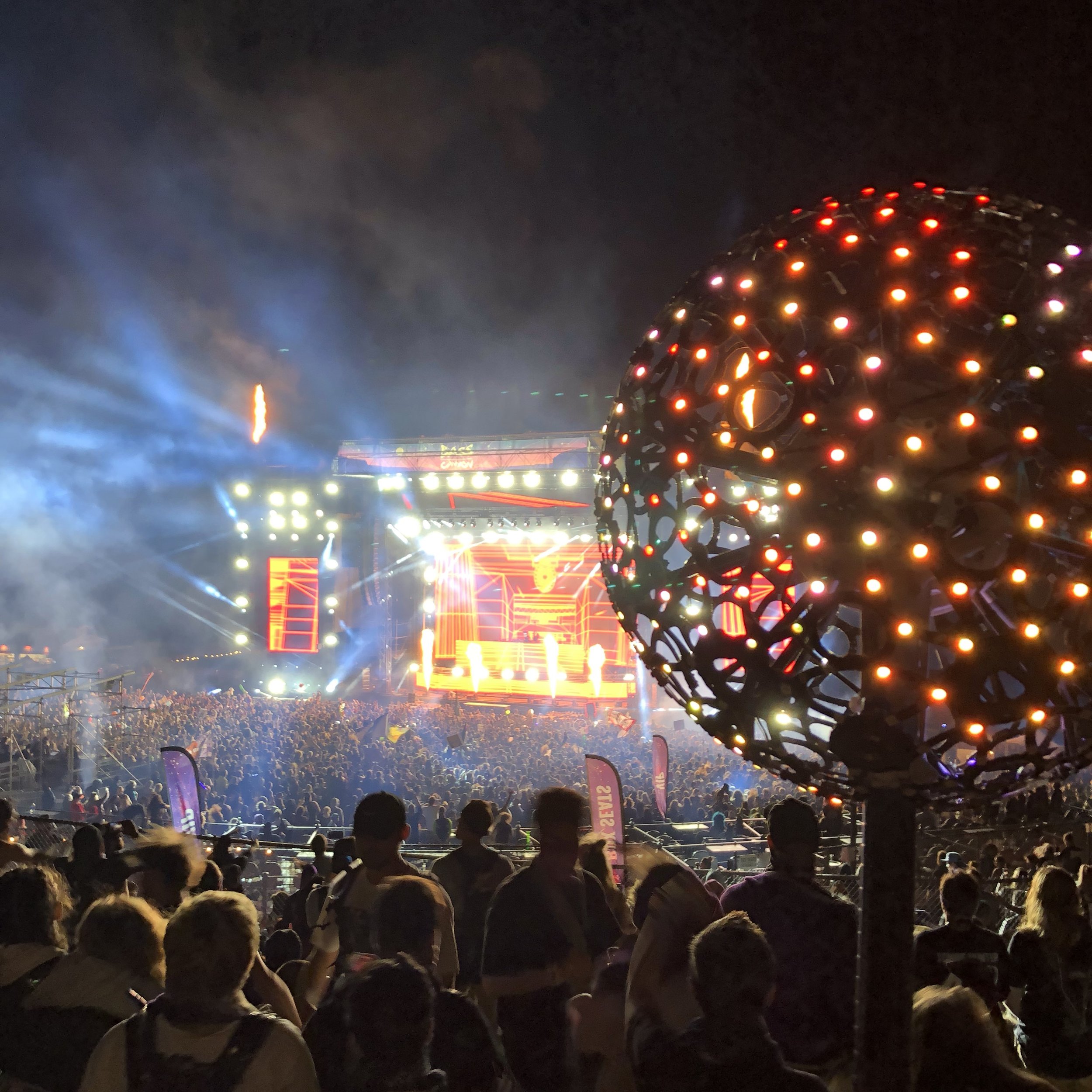
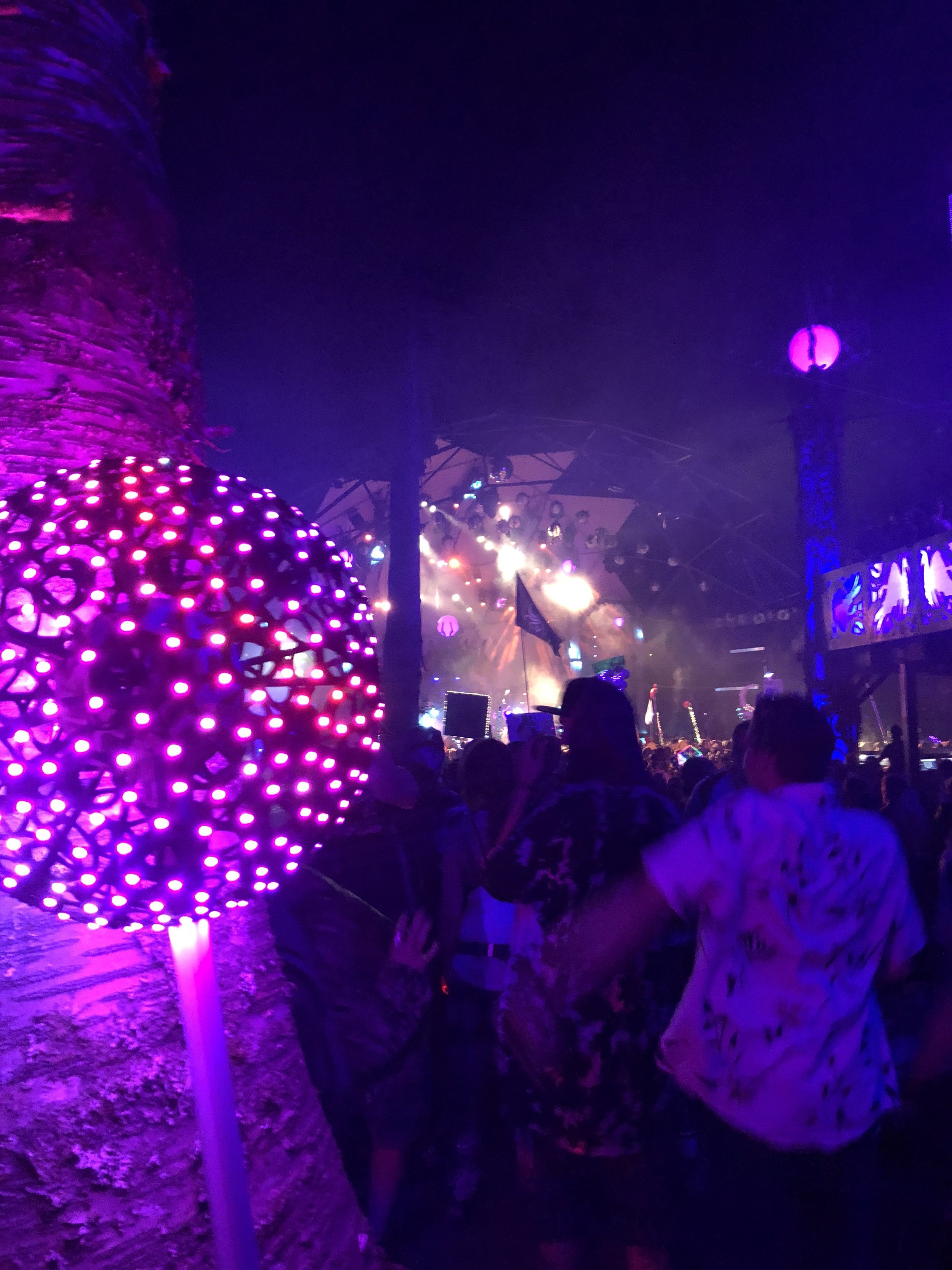
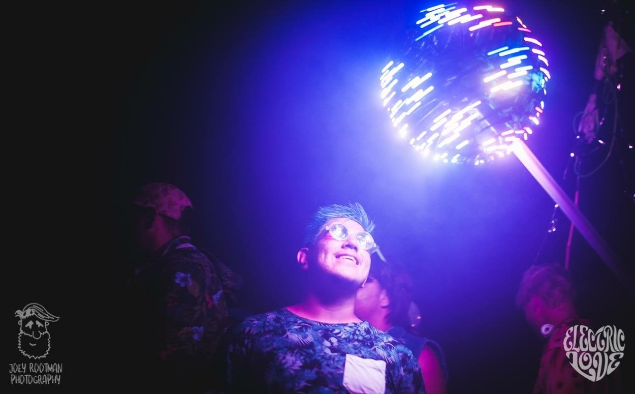
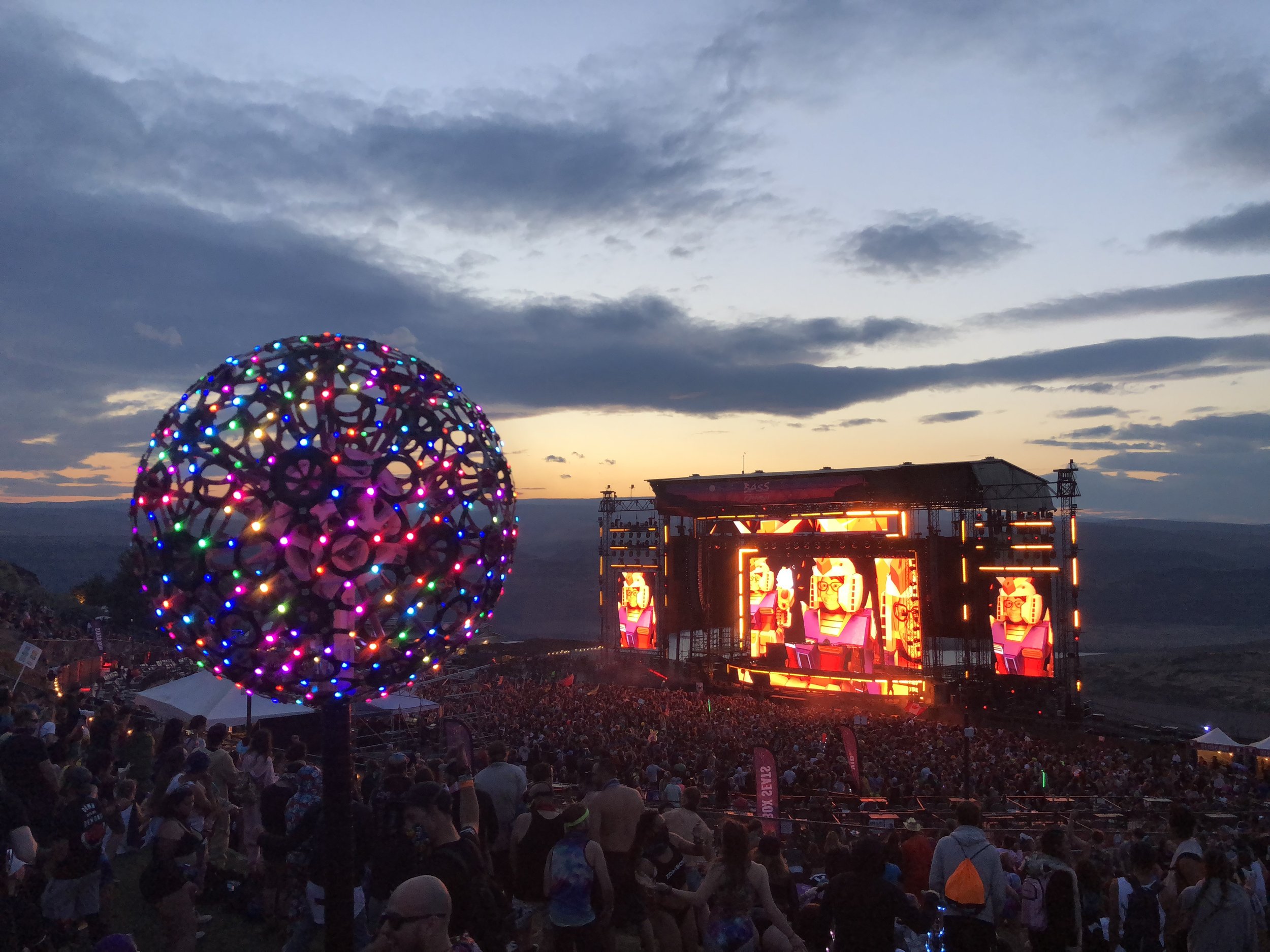
The finished product! It took a lot of work to build it all again, but ultimately it was well worth it. This version is so much lighter and I can easily hold it with one arm; dancing with it is a lot of fun. Because it's not tethered to a backpack I can spin it which is really fun. My biggest stress test of the battery was during Paradiso 2018 when I forgot the charger but it ended up going about 10 hours, lasting both nights (9pm-2am).
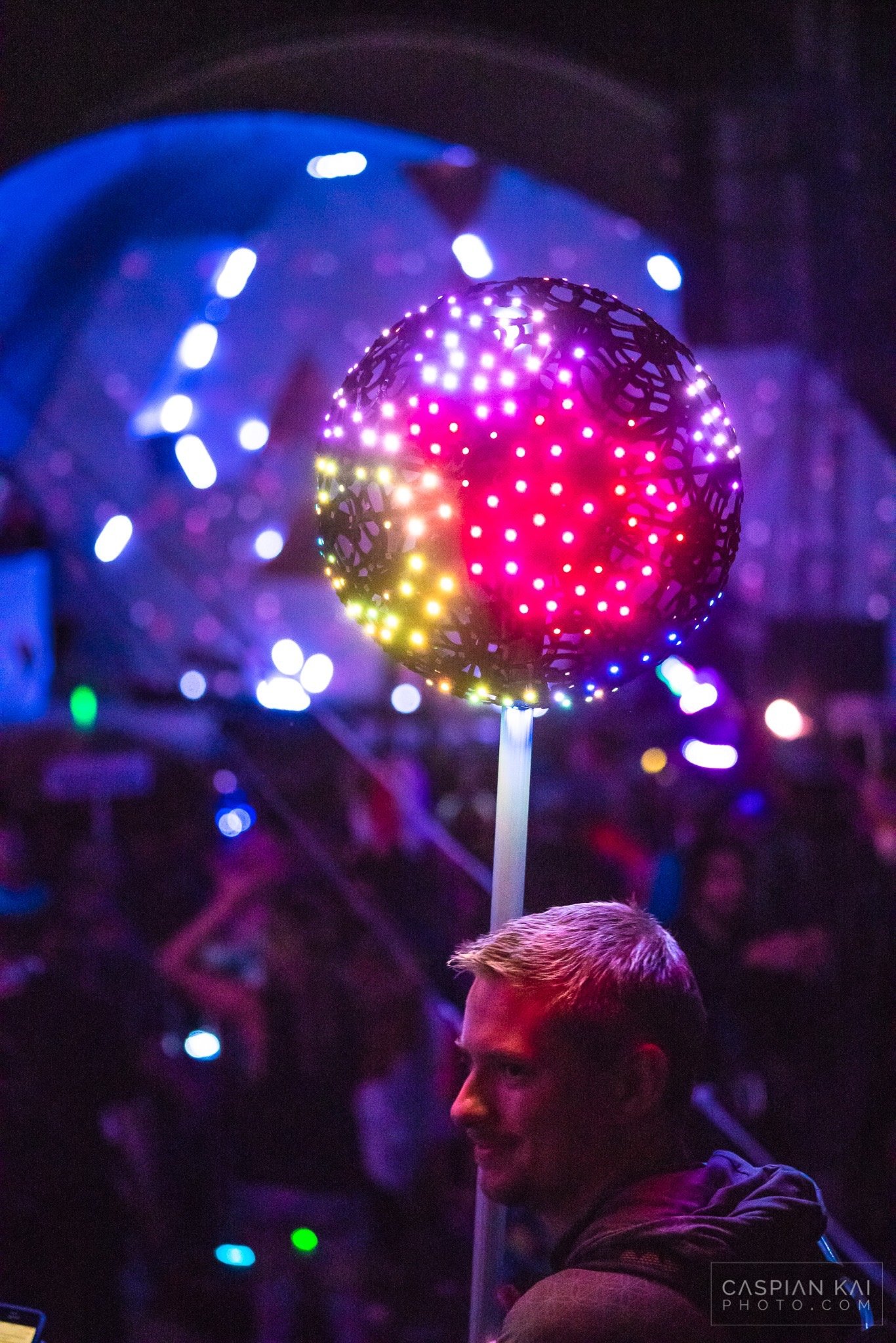
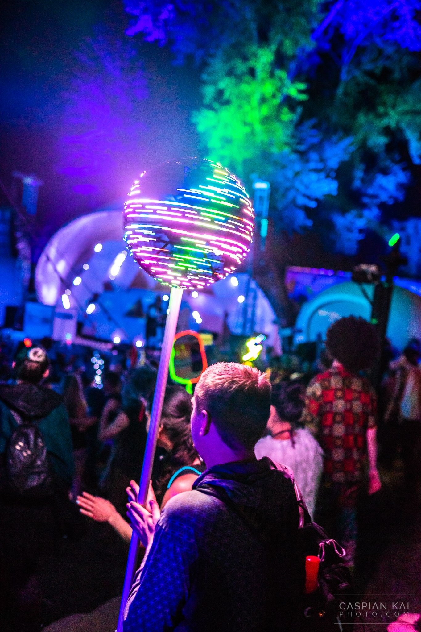
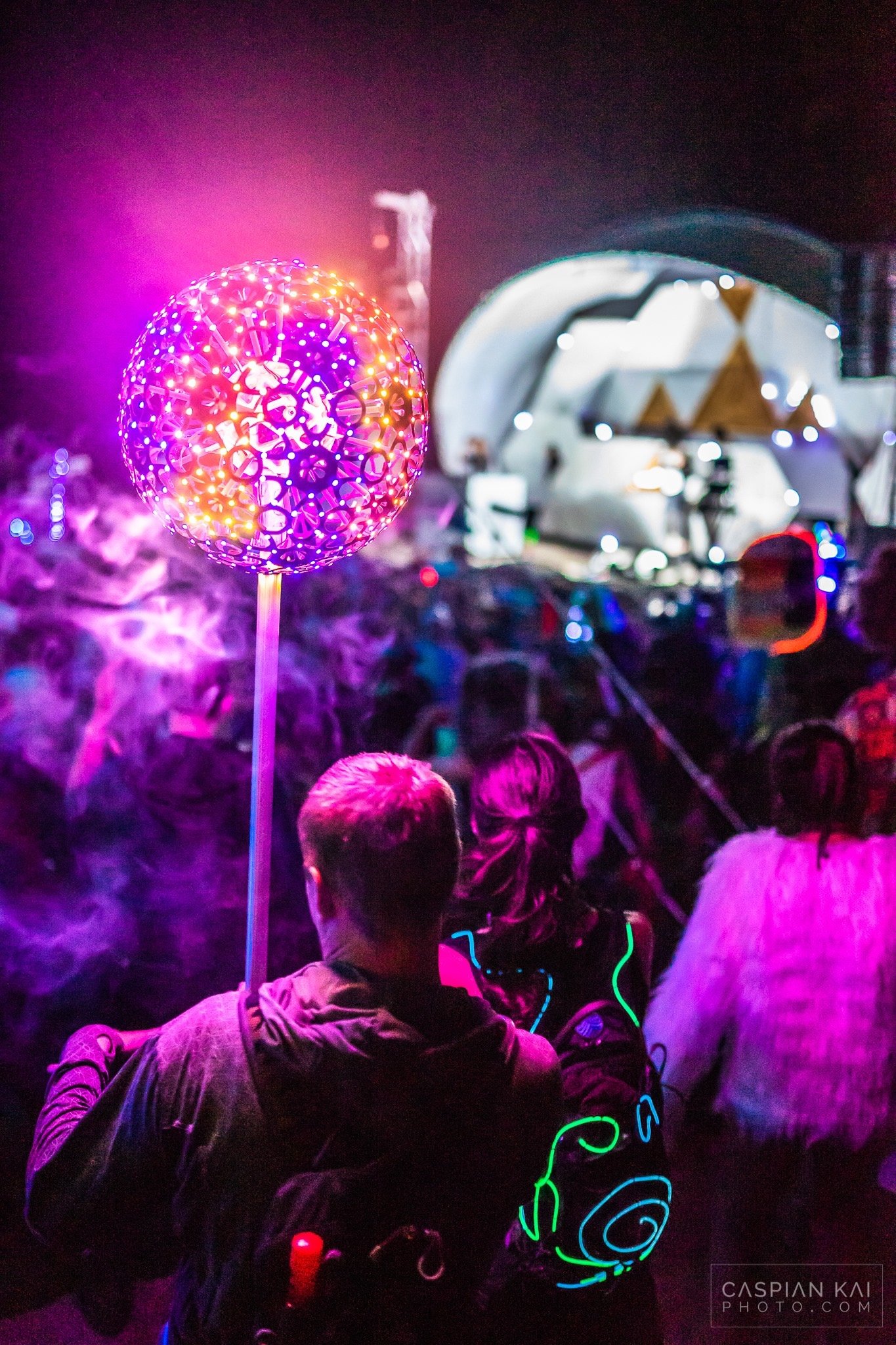
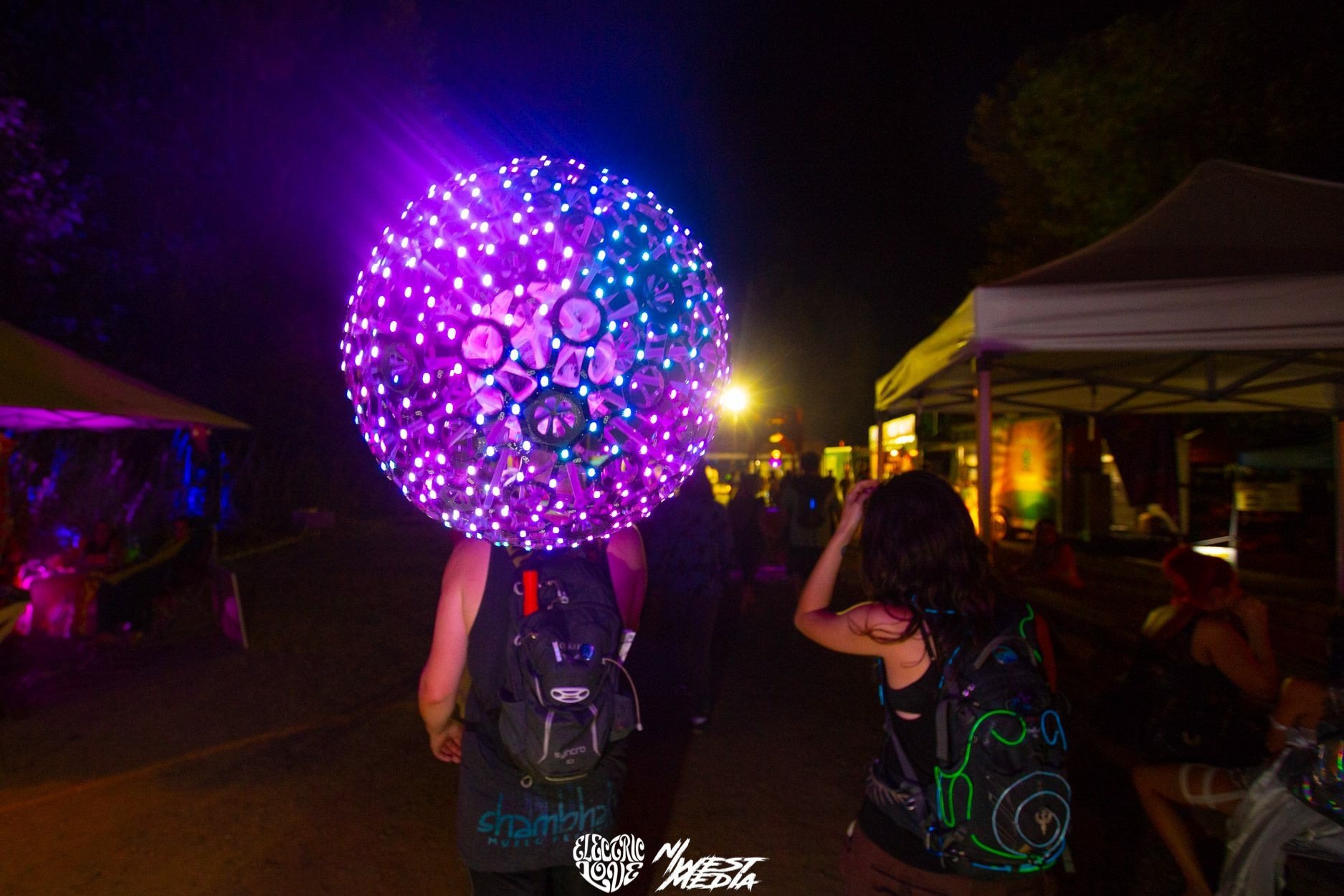
My first time bringing it out at a festival was Thursday night at Shambhala 2017. Unfortunately since I barely finished it time for the festival, I only had a simple animation that cycled through some different color palettes. Since then I have taken the time to add more animations which you can view in the gallery below.
Animation Gallery